Nowhere in the discussion of the flexagon of cycle greater than 3 has
the angle between the various sides played a crucial position. It is true
that we can create a relationship between the angles of the leaves and the
angles of the map polygons, but this relationship is soon seen to be purely
superficial. What is important in the map is not the shapes of the polygons
involved, but the number of sides they have, i.e., as predicted, the cycle.
It would seem therefore that, as in the triflexagons, we can change the
angles and lengths of the sides of the leaf polygons, yet maintain the
same mode of operation as in corresponding flexagons with regular leaves.
Of course, more units may be required to allow flexing at all the faces,
thus possibly decreasing the tendency of the flexagon to hold together at
certain other faces (the same was true in the triflexagons). However, we
will assume that an unlimited number of hands are available to operate the
flexagon once it has been constructed, and go right ahead without considering
practical difficulties. As in the triflexagons, we make the irregular
polygons coincide in the assembled flexagon, and use at least
![]() units, where
units, where ![]() is the smallest angle of the leaf.
is the smallest angle of the leaf.
What happens if not enough units are employed? Those faces at which
the angles pointed toward the center do not make up
![]() will not permit further flexing.
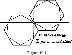
The effect on the map is as if the face were broken in
half (See fig. 10.1). At which faces will this occur? As in triflexagons,
any two map paths, lying in adjacent cycles the midpoint of whose common
side is in line with the midpoints of the two paths, represent faces having
like angles at the center of the flexagon. This fact can help us in the
manufacture of flexagons with irregular leaves. If we can indicate faces
on the map at which like angles of the flexagon will be pointed toward its
center, then each map path may be marked with the name of some such angle
corresponding to an angle of the irregular leaf. Each face of the map
must then be marked so that the angles of the hinge network polygons are
identified with angles of the leaves, the angles occurring in the same
order in the two places. One convenient way of doing this is by making
the map so that the hinge network polygons will be similar to the leaf
polygons. In building the plan, one leaf vertex between the incoming
hinge of each leaf polygon and the next hinge (where we are traveling about
the leaf in the direction, + or -, indicated by the sign corresponding to
that leaf) must have an angle equal to the leaf angle designated for that
leaf by the appropriate face in the map. Differently labeled angles in
the plan should never have a common vertex.
will not permit further flexing.
The effect on the map is as if the face were broken in
half (See fig. 10.1). At which faces will this occur? As in triflexagons,
any two map paths, lying in adjacent cycles the midpoint of whose common
side is in line with the midpoints of the two paths, represent faces having
like angles at the center of the flexagon. This fact can help us in the
manufacture of flexagons with irregular leaves. If we can indicate faces
on the map at which like angles of the flexagon will be pointed toward its
center, then each map path may be marked with the name of some such angle
corresponding to an angle of the irregular leaf. Each face of the map
must then be marked so that the angles of the hinge network polygons are
identified with angles of the leaves, the angles occurring in the same
order in the two places. One convenient way of doing this is by making
the map so that the hinge network polygons will be similar to the leaf
polygons. In building the plan, one leaf vertex between the incoming
hinge of each leaf polygon and the next hinge (where we are traveling about
the leaf in the direction, + or -, indicated by the sign corresponding to
that leaf) must have an angle equal to the leaf angle designated for that
leaf by the appropriate face in the map. Differently labeled angles in
the plan should never have a common vertex.
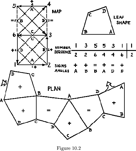
For example, to build the improper flexagon shown in fig. 10.2 with
the irregular polygon ![]() so that the angle
so that the angle ![]() would be at the center of
the flexagon at face 1, we would proceed as shown.
would be at the center of
the flexagon at face 1, we would proceed as shown.
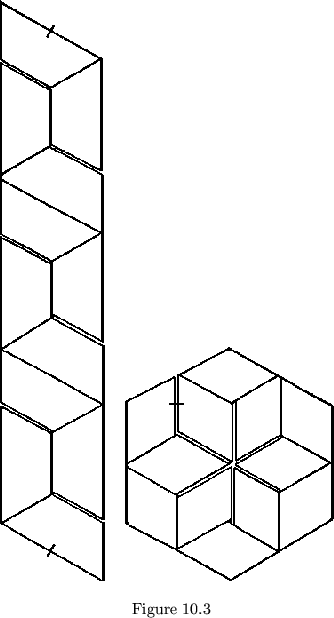
The proper tetraflexagon of order 4 has two interesting plans made from irregular leaves. The first is made from a hexagonal array of rhombuses and the second from a straight strip of isosceles trapezoids (see fig. 10.3). As is seen, the results of alternating leaf shapes are even more interesting in higher cycle flexagons than in triflexagons. They are so varied that other examples will be mentioned as needed, rather than all presented here.


