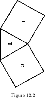
When we actually try to assemble a heteroflexagon, we find, naturally enough, that we are superimposing various different types of polygons. The problem inherent in this situation is seen when we try to fold together a strip of polygons such as that shown in fig. 12.2, folding it into a multicyclic pat structure like 213. There are a number of ways in which this problem has been attacked.

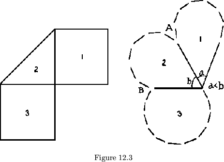
First, the shapes of the leaves could be changed. Thus, using the
pro-blem just cited, we could alter the leaves to one of the shapes shown
in fig. 12.3. As we can see, the alteration must allow leaf 1 to fit
between leaves 2 and 3. That is the only shape requirement. They do not
need to coincide or even be the same size. In fact, if we added in two
straight lines rather than one between ![]() and
and ![]() in fig. 12.3, the plan
would be made up of squares, and yet it would seem essentially unchanged.
Similarly, it could be any curve.
Then the ``class'' becomes unimportant at this point, since the number
of sides of the polygons used need have no effect on the way
the flexagon works.
in fig. 12.3, the plan
would be made up of squares, and yet it would seem essentially unchanged.
Similarly, it could be any curve.
Then the ``class'' becomes unimportant at this point, since the number
of sides of the polygons used need have no effect on the way
the flexagon works.
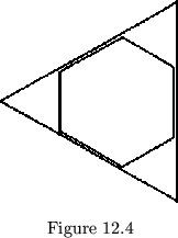
The second way that we could have solved the problem is necessary
only if we still wish to use regular leaf polygons. The basis for this
method is observation that, in leaves the number of whose sides are not
relatively prime, such as the triangle and hexagon shown in fig. 12.4, we
can trim the corners of the triangular leaves so that they look like
hexagons yet are hinged like triangles.
In this condition the leaves will fold
together without difficulty. For the general case, then, we find the Least
Common Multiple of the numbers corresponding to the types of polygons in
the plan and make all the leaves in the shape of these ![]() -gons. We thus
systematically chop off all the corners that might get in the way. This
method is quite interesting from the point of view of class, since the
alteration
makes the flexagon totally incomplete if two of the component cycles
are relatively prime but with different degrees of incompleteness in various
cycles. The class of this flexagon is now simply the
-gons. We thus
systematically chop off all the corners that might get in the way. This
method is quite interesting from the point of view of class, since the
alteration
makes the flexagon totally incomplete if two of the component cycles
are relatively prime but with different degrees of incompleteness in various
cycles. The class of this flexagon is now simply the ![]() . Therefore, the
face degrees, since they are still the same in terns of central angles,
cause there to be more hinge positions between incoming and outgoing hinges
at each face: if the number of these hinges had been
. Therefore, the
face degrees, since they are still the same in terns of central angles,
cause there to be more hinge positions between incoming and outgoing hinges
at each face: if the number of these hinges had been ![]() in the original
polygons, say
in the original
polygons, say ![]() -gons, then it will be
-gons, then it will be
![]() in the
in the
![]() -gons.
-gons.
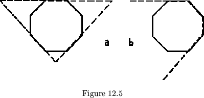
A combination of these first two methods gives what we know as incomplete flexagons. We make all the leaves in the shape of the polygon with the greatest number of edges and then use only an appropriate number of the sides for hinges, in cycles requiring fewer edges for the polygons. This is equivalent to changing the angles of one of the leaves and then cutting off corners (see fig. 12.5). Those made as in fig. 12.5b will not, of course, be able to make use of all the possible flexes. In this method, the class of all the ``incomplete'' cycles is changed.
The final method for dealing with conflicting hinges is the use of circular leaves. As we saw in the first method the only important factor in the shape of the leaves is the angle between hinges coming into and leaving each pat. Aside from this, the only requirement is that the leaves overlap each other, more or less, so that the flexagon is locked together and will not readily collapse. These requirements are both fully satisfied if we allow the leaves to assume the shape of overlying circles, hinged along tangents (fig. 12.6). The length of the hinges depends only on how crowded together the hinges are. We have thus, so to speak, eliminated all corners by using a polygon with an infinite number of sides. The angles between hinges may be computed from the map by imagining that the circular leaf is the circle inscribed in a polygonal leaf.
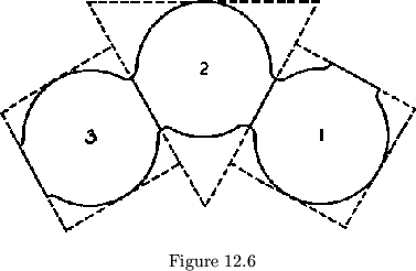
The use of circular leaves suggests several possible changes in notation. First, it would be very convenient to give the sign sequence in terms of degrees of the central angle between hinges in each leaf, thus removing re-ference to the kind of polygon used in the leaves of the flexagon, which is in this case quite ambiguous anyway. Also, we might suggest this ambigui-ty of class by using the map notation developed independently by R. F. Wheeler 12.1, who uses circles to represent the map cycles. The cycle circles are tangent to one another at various points, each of which represents a face. The arc between two faces represents a side. The arrows indicating direction of travel from face to face without turning the flexagon over now are the same as the direction of rotation of a gear assembly having the same appearance. Most interesting of all, the map and hinge network, when both built in this way from circles, are indistinguishable. Hence the building operation is considerably simplified; more so if the central angles between face points in the same cycle are used to indicate the class of the leaves used in that cycle.