There is a relationship between the map and the plan of the flexagon. If the plan changes, the map also changes, and usually the converse is also true. The number of leaves in the plan of one unit equals the order of the flexagon, which is equal to the number of vertices in the map.
Since all the thumbholes pass through the flexagon in a given direction,
clockwise or counterclockwise (the direction of winding up the flexagon is
constant for a given flexagon), if it is impossible to flex without rotating at
any given position, this means that the pat that would have to be slit in order
to allow us to proceed is of a single thickness. On the plan, then, the new color would be represented by a pair of leaves, on the backs of which would lie the two colors representing the two sides which the flexagon had exhibited before flexing. This is shown in relationship to the map in figure 3.1. It may be seen that this relationship provides an inductive method for building a flexagon having any desired map. First, however, it is convenient to have a system of orientation for working with the plan. We orient the triangles in the following manner: Draw arrows about the sides of one plan triangle, head to tail, and, for the surrounding triangles, draw arrows about each of these triangles in the direction indicated by the arrow on the side of this triangle which is common to it and the first triangle (see figure 3.2). Then, a triangle is called ``+'' if we leave it, in traveling along the plan, in the direction indicated by the arrow which is crossed in entering it, and ``-'' if left in the opposite direction. It can be seen that if, in any given situation, all
plusses are exchanged for minuses and viceversa, the array of triangles remains unchanged (though a mirror image case may result), since the choice of the original ``+'' direction is arbitrary. Notice that the strip of triangles corresponding to the sequence of signs ++++ ... or
![]() is a straight strip. Several other examples are shown in figure 3.3.
is a straight strip. Several other examples are shown in figure 3.3.


In adding a side to a flexagon, i.e., in slitting, two minus triangles are substituted for one plus (or two ``+'' for one ``![]() ''). The hexagon, or flexagon of order two, has the sign sequence
''). The hexagon, or flexagon of order two, has the sign sequence ![]() for its plan. The flexagon of order three, whose plan is a straight strip of nine triangles, has the sign sequence
for its plan. The flexagon of order three, whose plan is a straight strip of nine triangles, has the sign sequence
![]() , or, for the unit plan,
, or, for the unit plan, ![]() (since all units are identical, usually the sign sequence of only one unit is given). For the flexagon or order four, the (unit) sign sequence is
(since all units are identical, usually the sign sequence of only one unit is given). For the flexagon or order four, the (unit) sign sequence is ![]() . Notice that in obtaining each of these sign sequence from the previous example, either a
. Notice that in obtaining each of these sign sequence from the previous example, either a ![]() sequence was substituted for a
sequence was substituted for a ![]() , or a
, or a ![]() sequence replaced a
sequence replaced a ![]() .
.
Next we must invent a system for recording the ``color'' or number labeling each side of each leaf. This is done by drawing a line and placing number falling on opposite sides of the plan, in order, on opposite sides of the line. Numbers on a given leaf will appear opposite each other across the line. This system is illustrated in figure 3.4. In substituting in a new side, one number in the split leaf remains stationary and the number opposite it becomes adjacent to it, in the new leaf. The two numbers representing the new side are placed together opposite the old numbers. For example, to find the number sequence corresponding to the flexagon of order five by adding a side to the flexagon of order four we would proceed as in figure 3.5. When one of the original numbers forms a pair of like numbers with another number in an adjacent leaf, the pair should be broken in the number moving process. The reason for this is seen if we observe a splitting operation carefully. The operation occurs at a single thickness, which is attached to the top of the second pat where the new thumbhole is to be created (see figure 3.6). Hence it and one of the next few leaves in the plan, which is the top leaf in the next pat, have one ``color'' or number in common. When the new thumbhole has been made, the side of the single pat with the common color upon it will now no longer be connected to the top portion of the second pat. When there are no common numbers in leaves adjacent to the given leaf, the given leaf will at least lie between the two leaves that share its colors or numbers with it (the number sequence being considered as cyclic). Then the two numbers on the given leaf should be separated as much as possible from the same numbers on other leaves. This is a generalization of the previous example.


Whenever a leaf is added, the remainder of the sequence to the right must be inverted, to retain the same relative position with the original numbers on the given split leaf. This means that the second unit must have a number sequence inverted in relation to the first if the number of leaves, ![]() , is odd. The reason for this is the fact that then
, is odd. The reason for this is the fact that then ![]() , the number of folds in the finished flexagon unit, will be odd. Thus odd order flexagons are (one-sided) Möbius bands of
, the number of folds in the finished flexagon unit, will be odd. Thus odd order flexagons are (one-sided) Möbius bands of ![]() half twists (one of the possible half twists is left out to make each inter-pat hinge).
half twists (one of the possible half twists is left out to make each inter-pat hinge).
Combining the sign sequence and the number sequence for the flexagon or order three and for the order four flexagon, we find the results shown in figure 3.7. The plan of a flexagon of order 15 has been constructed for the reader by this method in Appendix B, to illustrate its useful application.

This system can be used to produce any flexagon, but it is nevertheless very complex and bulky. The expenditure of effort can be reduced considerably by using a device known as the Tukey triangle network. This network is actually a map of the hinging of the flexagon.
The traversing of a path in the map was initially said to represent a flexing operation. However, there is another way of looking at this. Each path can be said to represent that position of the flexagon at which the sides at either end of the path in question are the sides exhibited con the front and back of the flexagon in the given position. In this case, flexing is the changing from one path to another and rotation is represented, as before, by the choice of where to go next. Let us now represent each path by its midpoint only, and then let us connect these points in the various ways that the flexing operation can be carried out, i.e., by lines between the midpoints of the sides of each map triangle (see figure 3.8). A sequence of flexes uninterrupted by a rotation is now equivalent to a long straight line in the new network. During a repeated flexing operation only one hinge is used to join pats at other places (inter-pat hinges) than the thumbholes that are used. Hence one line in this new network, called the Tukey triangle network after its inventor, John Tukey, represents the use of one hinge for a number of flexing equal to the number of paths which have been used in the network. It may be convenient at this point to refer to the chart given in figure 2.8.

It is interesting to notice that a hinge folds together different directions on opposite sides of its network line in the Turkey triangle network.
This network follows exactly the Tuckerman traverse for any given flexagon. That is, the path in the network obtained by traveling along one line to its end and then traveling along the line meeting it at its end to a third line, and so forth, is identical to the path followed when the Tuckerman traverse is used. The network then has just ![]() lines, one for each hinge in the unit. Since the ends of the various network lines are the only positions at which new sides can be added, and since these are the spots where further flexing cannot take place without a rotation first, these are the only places at which one of the two pats in each unit is a single thickness. Being unable to flex without rotating is an indication of a pat of single thickness - the absence of a thumbhole - in every case. Now if we travel to a single pat, then rotate, then travel along the network in a straight line until we reach another single thickness, we have actually shifted from one hinge along the plan to the next, for the rotation changes the constant hinge from the hinge on one side of the single leaf to that on the other side. Using this
new hinge we have traveled to another single thickness, which can only be the next leaf in line along the plan, for it has a hinge in common with the last single leaf. Thus we visit consecutively all
lines, one for each hinge in the unit. Since the ends of the various network lines are the only positions at which new sides can be added, and since these are the spots where further flexing cannot take place without a rotation first, these are the only places at which one of the two pats in each unit is a single thickness. Being unable to flex without rotating is an indication of a pat of single thickness - the absence of a thumbhole - in every case. Now if we travel to a single pat, then rotate, then travel along the network in a straight line until we reach another single thickness, we have actually shifted from one hinge along the plan to the next, for the rotation changes the constant hinge from the hinge on one side of the single leaf to that on the other side. Using this
new hinge we have traveled to another single thickness, which can only be the next leaf in line along the plan, for it has a hinge in common with the last single leaf. Thus we visit consecutively all ![]() leaves in the plan in a calculable manner. To see this it may be handy to experiment with a flexagon in which consecutive leaves in the plan are labeled with consecutive numbers. When the Tuckerman traverse is performed upon this flexagon the preceding result should become apparent.
leaves in the plan in a calculable manner. To see this it may be handy to experiment with a flexagon in which consecutive leaves in the plan are labeled with consecutive numbers. When the Tuckerman traverse is performed upon this flexagon the preceding result should become apparent.
Suppose we are given a flexagon, and we want to find its number and sign sequences without dismantling it. Since we know how to encounter consecutive plan triangles, all we need to do is to copy down the two numbers or colors found on either side of each single thickness in the order we meet them. Thus we can identify the numbered leaves in the plan with identifiable faces of the flexagon. Our next problem is to identify these faces with corresponding positions in the map. These positions of course are those at the ends of the hinge lines in the Tukey triangle network. Furthermore, the order in which these faces are encountered is, of course, the order found in following the network. Each leaf of the plan, face of the flexagon, or vertex of the hinge network corresponds to two sides. It is our next problem to devise a method of labeling these sides. For the sake of consistency and convenience,
we adopt the following convention: the sides are numbered consecutively from 1 to ![]() about the outer edge of the Tukey triangle network, each side corresponding to a vertex of the map. We can now see that for each side there are two single-leaf flexagon positions, since each map vertex is at the periphery of the map and is therefore bordered along the outside by two paths radiating from it. Furthermore, each of the faces represented by these map boundary lines, which correspond to network vertices, can be labeled by two consecutive numbers, denoting the sides showing at the time that the given face is exposed. Thus we tie the labeling of the map to the labeling of the plan. As yet, however, we do not know which of these two consecutive numbers will be placed on which side of the leaf in the plan. For the sake of convenience we will momentarily employ the convention of using only one of these two numbers if possible; specifically, the lower one. In this way the number for both sides will be determined using only one piece of information; the unnamed side for each face is always the one named plus one.
about the outer edge of the Tukey triangle network, each side corresponding to a vertex of the map. We can now see that for each side there are two single-leaf flexagon positions, since each map vertex is at the periphery of the map and is therefore bordered along the outside by two paths radiating from it. Furthermore, each of the faces represented by these map boundary lines, which correspond to network vertices, can be labeled by two consecutive numbers, denoting the sides showing at the time that the given face is exposed. Thus we tie the labeling of the map to the labeling of the plan. As yet, however, we do not know which of these two consecutive numbers will be placed on which side of the leaf in the plan. For the sake of convenience we will momentarily employ the convention of using only one of these two numbers if possible; specifically, the lower one. In this way the number for both sides will be determined using only one piece of information; the unnamed side for each face is always the one named plus one.
Notice that during one ``roll'' (the repeated use of one set of hinges for flexing as long as possible without rotating) the two leaves in each unit which make up the single-leaf pats in the positions at the beginning and end of the roll do not change pats at any time during the roll. However, with each flex all the pats are inverted, with the exception of the portion of one pat which changes pats in the flex. Therefore the relative position (right side up or upside down) of the two connected single leaves remains unchanged. Then if we can derive a statement as to which side of the plan the lower number in the second face will occupy in relation to the side of the plan occupied by the lower number in the first face, this relationship will always be true.
The numbering of the sides is in general like that shown in figure 3.9. Suppose we start at position ![]() and proceed along hinge line
and proceed along hinge line ![]() to its end. Then two outcomes are possible: If it takes us an odd number of flexes to reach the new position
to its end. Then two outcomes are possible: If it takes us an odd number of flexes to reach the new position ![]() , the arrows directed along the paths of the map indicate that the lower side number in position
, the arrows directed along the paths of the map indicate that the lower side number in position ![]() will occupy the same physical surface ( top or bottom) as the lower side number of the original position,
will occupy the same physical surface ( top or bottom) as the lower side number of the original position, ![]() . The opposite will be true if there are an even number of flexes in the process; the new lower number will be on the opposite surface (top or bottom) of the flexagon. Also, we must consider that with each flex both single pats are inverted, as we have seen before. Thus although for an odd number of flexes between consecutive single-pat positions it would seem that the lower-numbered sides would be not only on the same surface of the flexagon but on the same side of the plan, this second factor, by inverting the plan in the odd case, acts to cancel the effect of oddness; in both even and odd cases the lower-numbered side of each leaf will lie on the opposite side of the plan from the lower-numbered surface of the preceding (adjoining) leaf in the plan. We finally see that the lower side numbers of the single pat faces will appear on alternate surfaces of the plan, from one leaf to the next. Then if we are given these lower numbers, we can recreate the number sequence of the flexagon rather easily, by placing these numbers on alternate sides of the line and then filling in the missing numbers with the numbers consecutively following those across the line. This filled-in number represents the side in each face that was momentarily neglected.
. The opposite will be true if there are an even number of flexes in the process; the new lower number will be on the opposite surface (top or bottom) of the flexagon. Also, we must consider that with each flex both single pats are inverted, as we have seen before. Thus although for an odd number of flexes between consecutive single-pat positions it would seem that the lower-numbered sides would be not only on the same surface of the flexagon but on the same side of the plan, this second factor, by inverting the plan in the odd case, acts to cancel the effect of oddness; in both even and odd cases the lower-numbered side of each leaf will lie on the opposite side of the plan from the lower-numbered surface of the preceding (adjoining) leaf in the plan. We finally see that the lower side numbers of the single pat faces will appear on alternate surfaces of the plan, from one leaf to the next. Then if we are given these lower numbers, we can recreate the number sequence of the flexagon rather easily, by placing these numbers on alternate sides of the line and then filling in the missing numbers with the numbers consecutively following those across the line. This filled-in number represents the side in each face that was momentarily neglected.

To determine the lower numbers and the order in which they fall, it is only necessary to follow the hinge network and to copy down the lower number at each vertex in the order they are arrived at. This process is simplified if the vertices of the Tukey triangle network are themselves numbered with the lower number of the vertex only. This is easily done, as shown in figure 3.10. Thus, if we are given any map, we can now construct the number sequence of the flexagon plan having this map. Upon closer analysis it will be found that this method of obtaining the number sequence is quite analogous to that developed previously, although it is considerably simpler.
We have yet to consider the problem of the actual shape of the plan; that is, the derivation of the flexagon's sign sequence. To obtain this from the map we again use the Tukey triangles.

Reference was previously made to the fact that alternate flexings invert any given leaf, provided it be one that is not moved between pats in the process. This means that if one group of hinges is used consistently, as in a roll, the two pats in each unit will rotate ![]() about the axis formed by that perpendicular bisector of the constant hinge in each unit which passes through both of the unit's pats (see figure 3.11). Let that angle of each of the leaves which is at the flexagon's center at some given time be labeled ``A''. Then when a flexing (and thereby a rotation of the pats about the aforementioned axis) occurs a new set of angles, ``B'', will be found at the flexagon's center. With repeated flexing each of these angles will appear alternately at the center and at the outer edge of the flexagon, as was seen in the last chapter. If we maintain the same constant hinge, there are now only two possible central angles for single pats. Let us assume that at one of the two single-pat positions the angles ``A'' are at the center of the flexagon. Then the angle between the two hinges bounding the single leaf will be labeled ``A''. We now flex along a single Tukey triangle network line to the other single pat. If the number of flexes used to reach this position was even, the new single leaf will also have angle ``A'' toward the center. If the number of flexes was odd, the angle between the two hinges is marked ``B''. We now recall that these two single leaves are connected by the constant hinge. Then we can determine the hinging of these two triangles in relation to one another, since we know that the first single leaf is hinged at angle ``A'' and that angle ``A'' of the first has the same vertex as angle ``A'' of the second (as angle ``B'' of the first has the same vertex as angle ``B'' of the second). This leaves two possibilities for the final hinging of the second leaf, as seen in figure 3.12. We can see from this diagram that the first alternative (even number of flexes in the roll) corresponds to a pair of unlike signs in the sign sequence and that the second possibility (odd number of flexes) corresponds to a pair of like signs in the sign sequence.
Thus the sign sequence can be determined by the evenness or oddness of the number of flexes connecting consecutive single-pat positions.
We must now find a way of determining this from the Tukey triangle network.
about the axis formed by that perpendicular bisector of the constant hinge in each unit which passes through both of the unit's pats (see figure 3.11). Let that angle of each of the leaves which is at the flexagon's center at some given time be labeled ``A''. Then when a flexing (and thereby a rotation of the pats about the aforementioned axis) occurs a new set of angles, ``B'', will be found at the flexagon's center. With repeated flexing each of these angles will appear alternately at the center and at the outer edge of the flexagon, as was seen in the last chapter. If we maintain the same constant hinge, there are now only two possible central angles for single pats. Let us assume that at one of the two single-pat positions the angles ``A'' are at the center of the flexagon. Then the angle between the two hinges bounding the single leaf will be labeled ``A''. We now flex along a single Tukey triangle network line to the other single pat. If the number of flexes used to reach this position was even, the new single leaf will also have angle ``A'' toward the center. If the number of flexes was odd, the angle between the two hinges is marked ``B''. We now recall that these two single leaves are connected by the constant hinge. Then we can determine the hinging of these two triangles in relation to one another, since we know that the first single leaf is hinged at angle ``A'' and that angle ``A'' of the first has the same vertex as angle ``A'' of the second (as angle ``B'' of the first has the same vertex as angle ``B'' of the second). This leaves two possibilities for the final hinging of the second leaf, as seen in figure 3.12. We can see from this diagram that the first alternative (even number of flexes in the roll) corresponds to a pair of unlike signs in the sign sequence and that the second possibility (odd number of flexes) corresponds to a pair of like signs in the sign sequence.
Thus the sign sequence can be determined by the evenness or oddness of the number of flexes connecting consecutive single-pat positions.
We must now find a way of determining this from the Tukey triangle network.


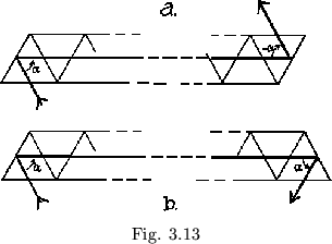
The number of flexes along a given hinge line is equal to the number of map triangles traversed. If the number is even, we leave the hinge line on a line parallel to that from which we entered it. If then we consider the angle between the hinge line by which we approach a vertex and the hinge line by which we leave the vertex, an even number of flexes between the vertices will make the angle at one vertex the negative of the angle at the other (see figure 3.13a). Conversely, odd numbers of flexes between vertices involve equal angles (figure 3.13b). We can now determine the evenness or oddness by letting a clockwise angle between hinge lines represent say a positive leaf, a counterclockwise angle a negative leaf. Each sign may be placed in the network at the vertex which determines its direction; this is the vertex of the appropriate leaf. If a sequence is now made of the signs encountered in passing through the hinge network, in the order they are come upon, this sign sequence will be identical with that produced by the more difficult method developed earlier.
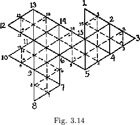
Now that we have worked out this new method, we can do the same problems as before in a much simpler fashion. Choosing as an example the same flexagon of order 15 treated in Appendix B, we first draw the Tukey triangle network and name the vertices with the lower of the two numbers at either side, so that 1 can be added in completing the number sequence (see figure 3.14). Next, traversing the Tukey triangle network, starting at one, and numbering alternate leaves upside down, we get:
| 1 | 12 | 13 | 8 | 10 | 14 | 2 | 15 | ||||||||
| 4 | 11 | 7 | 6 | 9 | 5 | 13 | 1 |
We now add 1 to each member to obtain the numbers lying on the other side of the leaves:
| 1 | 5 | 12 | 12 | 13 | 8 | 8 | 7 | 10 | 10 | 14 | 6 | 2 | 4 | 15 | 2 |
| 2 | 4 | 13 | 11 | 14 | 7 | 9 | 6 | 11 | 9 | 15 | 5 | 3 | 3 | 1 | 1 |
We next mark the angular direction between the incoming and outgoing lines at each vertex of the hinge network in the same order as that followed by the each vertex of the hinge network in the same order as that followed by the number sequence (see figure 3.14). If we now associate the number and sign sequences we obtain the sequence:
| 1 | 5 | 12 | 12 | 13 | 8 | 8 | 7 | 10 | 10 | 14 | 6 | 2 | 4 | 15 | 2 |
| 2 | 4 | 13 | 11 | 14 | 7 | 9 | 6 | 11 | 9 | 15 | 5 | 3 | 3 | 1 | 1 |
| - | - | + | + | - | - | - | + | + | + | - | + | - | - | - | - |
If we now remember that terms in this sequence which are separated by ![]() terms, where
terms, where ![]() is the order of the flexagon, represent identical leaves, we can see that the sequence is cyclic and identical to that obtained in Appendix B.
is the order of the flexagon, represent identical leaves, we can see that the sequence is cyclic and identical to that obtained in Appendix B.
In assembling the flexagon, the plan is repeated twice, cut out, taped together, and labeled according to the number sequence. It is important to notice that if the number of sides is odd, all the number sequence terms are reversed during the first repetition, with numbers falling on opposite sides of the strip from the usual position. The numbers are read off the map in this order on the second time around the Tukey triangle network. In flexagons with an even number of sides, there is no such disturbance. This is the reason for always including a small portion of the first repetition each time we write a sequence: oddness or evenness of the order ![]() must be kept in mind.
As an example of this effect, we give the full sequences for the flexagon of order
must be kept in mind.
As an example of this effect, we give the full sequences for the flexagon of order ![]() (
(![]() odd):
odd):
| 1 | 3 | 5 | 4 | 4 | 2 | 2 | 1 | 3 | 5 | 1 | 3 | 5 | 4 | 4 |
| 2 | 2 | 1 | 3 | 5 | 1 | 3 | 5 | 4 | 4 | 2 | 2 | 1 | 3 | 5 |
| + | - | - | - | + | + | - | - | - | + | + | - | - | - | + |
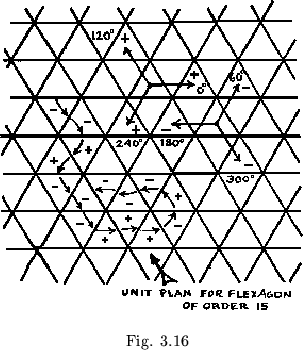
This technique of finding the plan of a given flexagon from its map still leads to problems. The first to overcome is the clumsiness of the oriented triangle system. It will be seen that if alternate triangles are shaded, checkerboard style, as in figure 3.15, the arrows about the dark triangles go in one direction and those about the light triangles in the other. Moreover, all the dark triangles stand on a vertex, whereas all the light triangles stand on a base. Using this observation we can now establish a new method of orienting the triangles. In this system arrows are drawn in the plan from the midpoint of each hinge to the midpoint of the next, so that the arrows pass along the length of the plan, one arrow leading to the next. Then arrows at angles of ![]() ,
, ![]() , and
, and ![]() from the horizontal are considered ``+'', are the triangles containing them, and those at angles of
from the horizontal are considered ``+'', are the triangles containing them, and those at angles of ![]() ,
, ![]() , and
, and ![]() from the horizontal are considered ``-'' (see figure 3.16).
from the horizontal are considered ``-'' (see figure 3.16).

There is a group of problems concerned with translating information given in one manner into another form. The forms used thus far include the map, Tuckerman tree, Tukey triangle network, sign sequence, number sequence, and plan. One thing clearly indicated in all these forms is the order of the flexagon, ![]() . It equals the number of vertices in the map, the number of lines in the tree plus 3, the number of exterior vertices in the triangle network, the number of signs or pairs of numbers in the two sequences, and the number of leaves in the unit plan.
. It equals the number of vertices in the map, the number of lines in the tree plus 3, the number of exterior vertices in the triangle network, the number of signs or pairs of numbers in the two sequences, and the number of leaves in the unit plan.
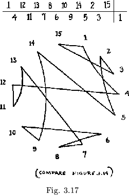
Given either the map, the tree, or the Tukey triangle network, the other two are easily formed by construction. The plan is equivalent to the sign and number sequences together. Given the map, the sequences can be found by the methods just described. The main problem, then, is to find the map, given either sequence. In order to establish a preliminary correlation between the number sequence and the map, we may try to use the fact that a side on the map which is touched by only two paths is always represented in consecutive plan leaves. There can be no more than ![]() but no fewer than two such sides. However, given the number sequence, we can do much better than this, by using the following process: We first select the lower of the two numbers in each pair of numbers lying opposite each other in the sequence. These numbers fall on alternate sides of the central line. Then, after making a ring of the numbers from
but no fewer than two such sides. However, given the number sequence, we can do much better than this, by using the following process: We first select the lower of the two numbers in each pair of numbers lying opposite each other in the sequence. These numbers fall on alternate sides of the central line. Then, after making a ring of the numbers from ![]() to
to ![]() , arranged consecutively, we draw a path connecting the lower numbers in the number sequence, in the order in which they occur in the number sequence. The figure thus formed is the Tukey triangle system (see figure 3.17). This method may be deve-loped further into a strictly numerical method for finding the sign sequence directly from the number sequence, though the formulation of this method is so complicated that it easily pays to pass through the intermediate graphic step of the Tukey triangle network.
, arranged consecutively, we draw a path connecting the lower numbers in the number sequence, in the order in which they occur in the number sequence. The figure thus formed is the Tukey triangle system (see figure 3.17). This method may be deve-loped further into a strictly numerical method for finding the sign sequence directly from the number sequence, though the formulation of this method is so complicated that it easily pays to pass through the intermediate graphic step of the Tukey triangle network.
If we are to find the map of a given sign sequence there will generally be several solutions possible. For instance, the sequence + + + + + + + + + + + + produces four distinct flexagon maps. Before trying to find the map corresponding to an arbitrary sign sequence, however, let us try to decide
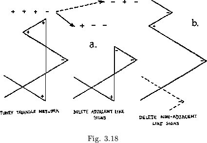
whether a given arbitrary sign sequence actually corresponds to a real flexagon. This problem is solved for the number sequence simply by translating it into map form, but with the sign sequence the solution is not so simple. Rather than the map we here employ a method know as ``reduction'' of the sign sequence. We can see that the combination + + in the triangle network could be replaced by a single - sign, as shown in figure 3.18a. This would delete one side from the flexagon, and is therefore the opposite of the slitting operation. However, where two signs, adjacent in the sign sequence, correspond to non-adjacent positions in the map, such as shown in figure 3.18b, the reduction to a single - sign has no meaning. In the case shown, the result is the sequence - + -, which, as is shown, is a degenerate triangle network. Therefore two like signs may be reduced only when a sequence of alternating + and - signs does not result, since such a sequence has no meaning. After the two deleted signs are replaced by one opposite sign, giving a new sign sequence, reduction may be carried out again. We may, of course, delete such a sequence as + + + + + + directly to the sequence - - -, rather than going through the steps - + + + +, - - + +, and - - -. Any replacing of
![]() by
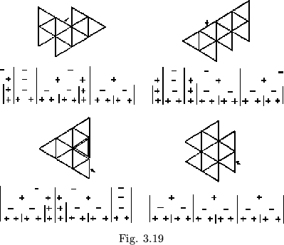
by ![]() , in other words, can give a true flexagon sign sequence only if the original sequence was also a true flexagon sign sequence. That is, if a sequence may be reduced in some way to a sequence of three like signs, or to any other known flexagon sequence, it represents some real flexagon, for we would then know that it could be produced by slitting. A reducible sequence will represent an identifiable flexagon, since the reduction process is characteristic of the flexagon. Now, if there exist two or more non-equivalent reduction processes for a given sign sequence, there exist an equal numbers of distinct corresponding flexagon maps. These may be reconstructed from the hinge networks of the flexagons which were identified as the result of the reduction process, by the reverse of reduction. which is the addition of new sides in the proper order, according to the path followed by the network. The problem of finding flexagons with a given sign sequence is thus reduced to the problem of finding distinct reduction patterns of the sign sequence. The analysis of the sequence + + + + + + + + + + + + is given as an example in figure 3.19, with the four resulting maps.
, in other words, can give a true flexagon sign sequence only if the original sequence was also a true flexagon sign sequence. That is, if a sequence may be reduced in some way to a sequence of three like signs, or to any other known flexagon sequence, it represents some real flexagon, for we would then know that it could be produced by slitting. A reducible sequence will represent an identifiable flexagon, since the reduction process is characteristic of the flexagon. Now, if there exist two or more non-equivalent reduction processes for a given sign sequence, there exist an equal numbers of distinct corresponding flexagon maps. These may be reconstructed from the hinge networks of the flexagons which were identified as the result of the reduction process, by the reverse of reduction. which is the addition of new sides in the proper order, according to the path followed by the network. The problem of finding flexagons with a given sign sequence is thus reduced to the problem of finding distinct reduction patterns of the sign sequence. The analysis of the sequence + + + + + + + + + + + + is given as an example in figure 3.19, with the four resulting maps.
There is also a trial-and-error method for finding the map of a given sign sequence. With a little practice, it may be used quickly and directly with rather good results. It involves the use of a plane marked off with equilateral triangles, with dots placed in each triangle of one of the three families made up of triangles whose vertices are opposite one another, as shown in figure 3.20. The dots identify the triangles in which they lie as potential members of the Tukey triangle network of the unidentified flexagon. The Tukey triangle network is then constructed by experimentation, from the sign sequence, each turn in the network being the vertex of a dotted triangle.

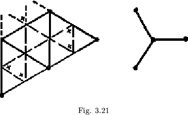
It may have been noticed in the reductions of the 12-sided flexagon's sign sequence above that each of the resulting maps is made up of various combinations of the basic unit shown in figure 3.21, combined in various ways starting from a single initial map triangle. Thus the Tuckerman trees are composed entirely of units such as the one also shown in figure 3.21. Each of the map units, taken singly, corresponds to the addition of four plus signs in the place of one. The four 12-sided flexagons, like all regular flexagons, have maps made up of non-equivalent combinations of this unit, and all combinations of this unit will, in turn, produce regular flexagons.
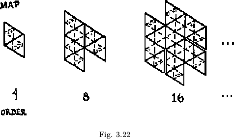
There are a great number of such families of flexagons that are produced using various groupings of basic patterns of signs or map triangles. An interesting example is the family of flexagons whose plans are made up of groups corresponding to the sign sequence + + - -. As regular flexagons are of order ![]() (
(![]() an integer), members of this family will be of order
an integer), members of this family will be of order ![]() . Of the members of this family, we will consider only those corresponding to the reduction, in one step, of each + + - - group to a + + + group.
That is, we can produce the maps of the flexagons in this family by adding a fourth vertex at every third vertex in the Tukey triangle network of the regular flexagons.
One sequence of maps thus produced is shown in figure 3.22. Since every third turn is doubled, all these doublings will occur on the same edge of the map.
. Of the members of this family, we will consider only those corresponding to the reduction, in one step, of each + + - - group to a + + + group.
That is, we can produce the maps of the flexagons in this family by adding a fourth vertex at every third vertex in the Tukey triangle network of the regular flexagons.
One sequence of maps thus produced is shown in figure 3.22. Since every third turn is doubled, all these doublings will occur on the same edge of the map.
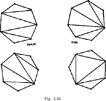
Three families of flexagons, classified according to the shapes of their maps, are worthy of mention. The first of these groups is produced by the end-to-end coupling of the map unit shown in figure 3.23 (with the possible addition of a final single triangle at the end of the chain), generating the long chain-like maps and triangle networks also shown in figure 3.23. In these, the ``chain'' flexagons, it is possible to visit all the sides without a rotation. In the face at one end of the long hinge line, all the leaves but one are wound about each other. As the long hinge line is followed, the leaves are reeled in from one pat and rolled up on the other. The sign sequence is + + - + - + - + . . .
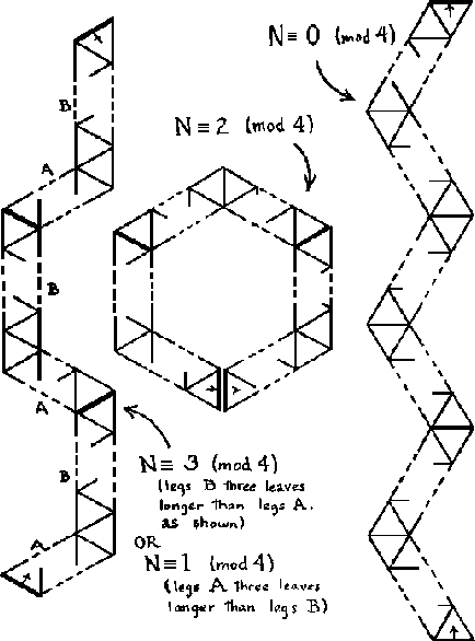
![]() (the last sign is + if the order is odd, - if it is even,), so that the unit plan winds around a single point, finally branching off at either end. There are four possible patterns for fastening the three-unit plan together, depending on the value of
(the last sign is + if the order is odd, - if it is even,), so that the unit plan winds around a single point, finally branching off at either end. There are four possible patterns for fastening the three-unit plan together, depending on the value of ![]() (mod 6); these are shown in figure 3.24.
(mod 6); these are shown in figure 3.24.


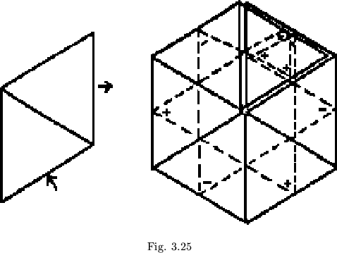
The second family is produced by tying the pairs of map triangles together, end to end, in another fashion. As with the chain flexagons, we may remove half of the last group of two triangles added, to allow the order of the flexagon to be either odd or even. As we see from figure 3.25, the map and Tukey triangle network will, if extended long enough, overlap themselves, but this may again be ignored. In these flexagons, ![]() of the
of the ![]() faces (or
faces (or ![]() out of
out of ![]() , if turning the flexagon over is allowed) exhibit the characteristic central side. If we choose to visit the paths radiating from this central side consecutively, we can, but after each flexing the flexagon must be turned over. The general sign sequence for these, the ``fan'' flexagons, is + + + + + . . .
, if turning the flexagon over is allowed) exhibit the characteristic central side. If we choose to visit the paths radiating from this central side consecutively, we can, but after each flexing the flexagon must be turned over. The general sign sequence for these, the ``fan'' flexagons, is + + + + + . . . ![]() - - - . . . . If
- - - . . . . If ![]() is odd, the middle signs will be
is odd, the middle signs will be ![]() : if
: if ![]() is even, the middle signs will be
is even, the middle signs will be ![]() , There are now just three ways of fastening the unit plans together (see figure 3.26).
, There are now just three ways of fastening the unit plans together (see figure 3.26).
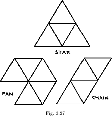
The third of these families is that of the regular flexagons produced by uniform doubling of a straight strip plan; the ``star'' flexagons.
These three families may be used to distinguish the three flexagons of order six, which are shown in figure 3.27. Flexagons of order less than six may be said to be included in all three families. For order greater than six, all flexagon maps may be described as some combination of the three types, linked together in various arrangements. Thus, after analysis of each linkage in the map, it is possible to describe almost instantly, more or less accurately, the plan of a given map or a map for a given plan.
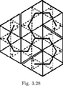
This may be helpful as a check or an aid to precise computation, The method is practicable, though it requires much practice for effective use. As an example of its application, let us look at what has been called the ``pinwheel'' flexagon. The map shows us that this flexagon is composed of three fans tied end to end as shown in figure 3.28. To find the sign sequence we simply find the sequence for each of the three fans, and then tie their ends together through use of the star flexagon-like central linkage. To make the linkage, we cut out the first group of two plus signs, ++, in each fan, and in their place add in the other two fans, similarly prepared.
The general form for the sign sequence of the pinwheel is then:
+ + + . . . ![]() - - - . . . + + . . .
- - - . . . + + . . . ![]() - - . . . + + . . .
- - . . . + + . . . ![]() - - . . . .
- - . . . .
This same general pattern may be modified to fit any three branch linkage, and the results are relatively easily applied to the plan.
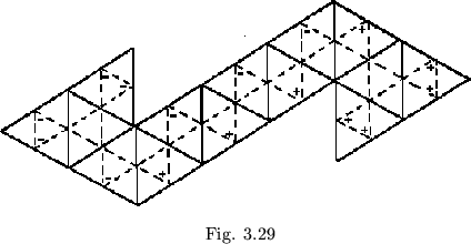
Another interesting group of flexagons is that formed by linking two star flexagons together by means of a chain, as shown in figure 3.29. In the plan, this corresponds to leaving the +-+-... whorl in straight strips whose length will correspond to the intricacy of the star fragments attached. The stars on either end of the whorl will each lose one sign.
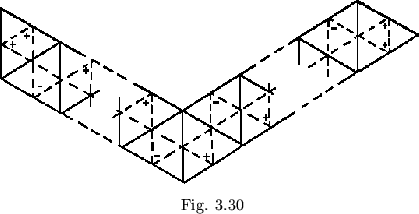
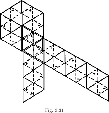
The interlinking of chain, star, and fan flexagons in various ways can lead to interesting results. The fastening of two chains of map triangles end to end at a ![]() angle produces, in the sign sequence, a series of alternating signs, followed by two like signs, followed by more alternating signs, followed by two like signs (see figure 3.30). The plan is a pair of overlapping
angle produces, in the sign sequence, a series of alternating signs, followed by two like signs, followed by more alternating signs, followed by two like signs (see figure 3.30). The plan is a pair of overlapping ![]() whorls. The break in the chain is shown by the change in direction of the whorl. If a fan-shaped strand is placed between and joining the two chains, as in figure 3.31, the straight strips connecting the ends of the two whorls in the plan are increased appropriately in length.
whorls. The break in the chain is shown by the change in direction of the whorl. If a fan-shaped strand is placed between and joining the two chains, as in figure 3.31, the straight strips connecting the ends of the two whorls in the plan are increased appropriately in length.
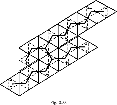
Chains may also be linked together by means of a cross path, as in figure 3.32. In this case, each chain sign sequence will be broken at some point. There will always be four pairs of like signs, which will be distributed according to the breaking points in the chains. The remaining signs will alternate. This means that there will be two whorls, probably of different sizes, connected by a simple crossover (a double sign, which allows us to leave a whorl). If more than two parallel chains are joined, the process becomes more complex.
If the plan is folded up backwards, all hinges being folded the wrong direction, the result is interesting, though it looks confusing. A side that had originally been labeled with a given number will instead be labeled with two different numbers, falling on alternate pats, and these two numbers will be the numbers of the sides adjacent to the original side along the outer edge of the map.
Thus if the side had originally been numbered ![]() , it will now be labeled half
, it will now be labeled half
![]() , half
, half ![]() .
.
Certain plans, having greater translational symmetry than is usual, can not only be folded up in the wrong direction, but the folding process may be translated along the plan by less than a unit. They may, so to speak, be folded up using the wrong hinges at the wrong time, but using the same folding pattern. The regular flexagons will clearly possess this property, and may be folded into flexagons having the usual maps but unusual coloring schemes. If, in this process, either the pattern of folding up the flexagon is essentially changed or the plan does not have the necessary symmetry, a flexagon having a different map may result; this is in a sense the way in which different flexagons may be folded from the same plan.
By now the reader has probably begun to wonder how many flexagons can be made of a given order ![]() . One clue to the solution of this problem is the fact that each of the various combinations of the
. One clue to the solution of this problem is the fact that each of the various combinations of the ![]() triangles in the map produces a different flexagon.
We therefore simply construct all possible distinct maps having this number of triangles. Since we have no direct method of finding distinct maps, we are forced to construct all the maps possible and then find which of them are distinct. Before we try to do this, though, we must be sure that we know how to tell whether or not two maps are equivalent. If should be clear that two maps, one of which is the other rotated about its center, are equivalent. So, also, are two maps each of which is the mirror image of the other. If two maps are not related in either of these ways, they represent different flexagons.
triangles in the map produces a different flexagon.
We therefore simply construct all possible distinct maps having this number of triangles. Since we have no direct method of finding distinct maps, we are forced to construct all the maps possible and then find which of them are distinct. Before we try to do this, though, we must be sure that we know how to tell whether or not two maps are equivalent. If should be clear that two maps, one of which is the other rotated about its center, are equivalent. So, also, are two maps each of which is the mirror image of the other. If two maps are not related in either of these ways, they represent different flexagons.
It has been pointed out that on a flexagon map each side is represented by a point along the outer edge of the map. This means that there are also as many outer paths as there are sides; i. e., the map is topologically a triangulated ![]() gon. Suppose that we desire to draw a map of a given flexagon. We start with one of the
gon. Suppose that we desire to draw a map of a given flexagon. We start with one of the ![]() sides and label an
sides and label an ![]() gon vertex with its color. We could have labeled the same vertex with any of the
gon vertex with its color. We could have labeled the same vertex with any of the ![]() colors; these possibilities correspond to the possible flexagons which are equivalent under rotation of the map. Once we have selected the first side, we have two positions in which one of the two sides adjoining it along the outer edge can be placed. If the second map side is placed in one direction from the first , the map will come out a mirror image of the map produced by placing it in the other direction. After these two sides have been placed, however, the remainder of the map is determined. This establishes the criteria for equivalence of maps given in the last paragraph.
colors; these possibilities correspond to the possible flexagons which are equivalent under rotation of the map. Once we have selected the first side, we have two positions in which one of the two sides adjoining it along the outer edge can be placed. If the second map side is placed in one direction from the first , the map will come out a mirror image of the map produced by placing it in the other direction. After these two sides have been placed, however, the remainder of the map is determined. This establishes the criteria for equivalence of maps given in the last paragraph.
It would seem, then, that the problem resolves to merely counting all possible triangulations of an ![]() gon, irrespective of rotations and reflections, and then dividing by
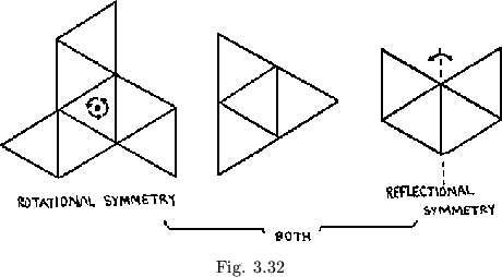
gon, irrespective of rotations and reflections, and then dividing by ![]() , the number of equivalent maps, thus produced. This method, however, neglects the fact that some maps, due to their symmetry, will not be influenced by rotations or reflections (see those shown in figure 3.33). These maps are not counted so many times as are the asymmetrical maps, during the preliminary estimate, so that dividing by
, the number of equivalent maps, thus produced. This method, however, neglects the fact that some maps, due to their symmetry, will not be influenced by rotations or reflections (see those shown in figure 3.33). These maps are not counted so many times as are the asymmetrical maps, during the preliminary estimate, so that dividing by ![]() will always give a low value. To correct for this, we will have to find out how many symmetrical maps there are of each order.
will always give a low value. To correct for this, we will have to find out how many symmetrical maps there are of each order.
Another approach would be working out the number of possible trees that would give legitimate Tuckerman trees. The number of possible plans will be related to the number or possible maps, though, as we have said, some (and for large ![]() , many) maps have the same plans.
, many) maps have the same plans.
These calculations are related to a long sequence of interesting and well-know combinatorial problems with interesting histories. Aside from flexagons, the general area concerns itself with such diverse things as folding up postage stamps, hydrocarbon isomers, election results, non-associative powers, electrical circuits, etc. We will not go into the details here of any of these problems.
The expressions finally obtained for the number of flexagons of order ![]() , using any of the possible methods, are very complicated, with various cases depending on
, using any of the possible methods, are very complicated, with various cases depending on ![]() (mod 6). To give an idea of the numerical results, though, there is only one flexagon apiece for
(mod 6). To give an idea of the numerical results, though, there is only one flexagon apiece for ![]() or
or ![]() .
We have seen the three of order six. There are four of order seven, 12 of order eight, and
.
We have seen the three of order six. There are four of order seven, 12 of order eight, and ![]() of order nine. From
of order nine. From ![]() on, though, the number begins to climb astronomically:
on, though, the number begins to climb astronomically: ![]() of order
of order ![]() ,
, ![]() of order
of order ![]() ,
, ![]() of order
of order ![]() ,
, ![]() of order
of order ![]() , and
, and ![]() of order
of order ![]() ; then
; then ![]() ,
, ![]() ,
, ![]() , and
, and ![]() .
.
The four distinct polygon triangulations for the heptagon (flexagon of order seven) are shown in figure 3.34.
