

Next: G-Flexagons
Up: Flexagon
Previous: The Pat Structure
Contents
The theories concerned with the flexagon committee's ``flexible
hexagons'' seemed at first to be a fairly complete description of the
flexagon family. Each assumes a more or less clear-cut definition of the
flexagon, from which it proceeds to deduce certain properties. However,
it has been found that, by altering the definitions used slightly, whole
new ``dimensions'' of flexagons can be discovered.
It may be best to clear up the haze surrounding the definitions of
flexagons now before they are extended any further. It should be clear
that the conditions of any definition will be determined by the object
itself. It will be impossible to give an absolute definition of flexagons
since it is a matter of taste what one wishes to include in this category.
As we proceed, we will come to count more and more strange figures under
the general heading ``flexagons''. Most of these are not included by definitions already considered; their only justification is the interesting results they produce. Of course, reason dictates that only figures related
to flexagons or including flexagons as a special case should be considered.
The first extension to be added in this section is hinted at by the
pat structure definition: A flexagon is an ordered pair of pats. This
pair is repeated twice to form the actual paper flexagon. Why then can
we not build a flexagon with the pair of pats in duplicate? Or in quadruplicate? It is soon found that there is no reason at all, flexagons
can be made with any number of units. More than four units cause appreciable overlapping of pats and produce relatively unstable models, but are
theoretically practicable. The four-unit flexagon does not lie flat, but
this makes it all the more fascinating, One-unit flexagons must be
operated in the imagination, or else cut  different times to reveal
all the faces.
The two-unit ``cup'' flexagon is built by joining the pats to form
a tetrahedral angle. Since the vertex cannot be ``pushed through'',
placing the inner surface on the outside, the outer side remains constant.
Flexing is always accomplished by pinching together pairs of adjacent pats
and occurs between the constant outer side and the variable inner side.
The map, therefore, presents the appearance of spokes emanating from the
central point representing the constant side, since no outer faces or
paths can be used. Because arrows adjacent along the spokes point in
different directions, the flexagon must be turned over after each flexing
to use the next spoke. The obvious way to take advantage of this is to
build a two-unit fan flexagon, which will have no unused sides.
The construction and operation of this fan flexagon suggest a
further possibility. During the entire operation of the flexagon, the
stacks of leaves remain on the outer side, slowly shifting between alternate
pats. These pats, due to the fashion in which they have been built,
can be constructed to incredible length. Until now, the physical limitation
of paper thickness had made it impossible to construct flexagons of
orders greater than 48 or so. However, utilizing the principle of the cup
fan flexagon, we can now build 2- (or 3-, if flexing is restricted to the
``cup'' pattern) unit flexagons of unlimited size. A three-unit flexagon
of order 658 has been built by the authors; all the sides can be exposed
but only  paths may be used, instead of the usual
  .
.
Another possibility, related to the cup flexagons, is the mixed
flexagon. Mixed flexagons are based on the observation that the units
used need not be identical. If they are different, each will have its
own map, and the map of each will partly coincide with those of the others.
If a11 three coincide at any face, this face will open out and lie flat.
For faces where only two of the maps coincide, the third unit will not
open out, and the flexagon will look like a cup flexagon. If only one
map occupies a face, it will not open out at all. To build mixed flexagons,
the three maps must be drawn with differently colored pencils, overlying
in the desired way. In copying down the sequences, all proceeds as
usual except that after each trip about the Tukey triangle network, one
must change maps. The tukey triangle network is drawn over all the maps,
but only the portion corresponding to the map being used is followed at a
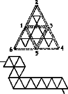
given time. A simple mixed flexagon is shown in fig. 5-1. Mixed flexagons
may be extended considerably by the use of more than  units.
| 2 |
2 |
3 |
1 |
5 |
3 |
4 |
4 |
6 |
6 |
2 |
2 |
4 |
4 |
5 |
| 3 |
1 |
5 |
6 |
6 |
1 |
5 |
3 |
1 |
5 |
3 |
1 |
5 |
3 |
1 |
| + |
+ |
- |
+ |
+ |
- |
+ |
+ |
+ |
+ |
+ |
+ |
+ |
+ |
- |
Figure 5.1
Just as the pat structure definition does not mention the number of
units in the flexagon, so also it neglects to say that the leaves must be
equilateral triangles. In dispelling this requirement, we open up another
new dimension.
The relative position of the vertices of the leaves within any given
flexagon is constant. Therefore, varying the angles of the triangles used
as leaves should make no difference in the operation of the flexagon. For
instance, a 45 - 45
- 45 - 90
- 90 flexagon of order 6 may be constructed quite
easily, by the doubling-over technique, from a strip such as the one shown.
(fig. 5.2) We have seen, by means of ``dots'', that various angles occupy
the center of the flexagon at various times. Varied angles provide an excellent form of ``dot''.

When the 45 angles of the 45
 - 45
- 45 - 90
- 90 flexagon are at the center, four units must be used, in order to prevent cup-flexagon-like operation.
When the 90
 angles are pointed toward
the center, there is, therefore, a
surplus of 360
 . A number of things may be done about this. The most
obvious is to ignore it and flex on. In this particular case, however,
opposite units may be laid flat and, with a half twist, the two middle units
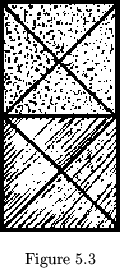
may be opened out flat. The final product is a bicolored rectangle (fig. 5.3).
This is typical of a second type of distortion of the flexagon. A flexagon
with more than 360 about its center may always be forced to lie flat by the following procedure: Simply fold a unit together, then fold together
the next two pats on either side of the first two, etc., just as was done
to distort the structure of the 3-equilateral flexagon,.
With care a flexagon of any number of sides, any number of units,
and any shape of triangle may be built. However, beyond order 3 in flexagons
of many units the structure is generally so easily distorted that the
flexagons are not worth the trouble of construction.
The irregular strip used in making a scalene or isosceles flexagon
of order 3 corresponds to the straight strip in equilateral flexagons. A
process has been developed to simplify the making of what will be called
by definition a ``straight'' strip; i.e., the strip of leaves corresponding
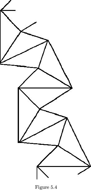
to a straight chain of equilateral triangles. Draw any triangles and label
the vertices  ,
,  , and
, and  . Then construct

etc. as in figure 5.4. This is continued until enough leaves have been
produced. To find by construction the number of leaves required for all
faces to have at least 360 about their centers, encircle the vertex of
the smallest angle and measure off around the circle to find the minimum
even number of arcs, equal to the arc of the smallest angle, which will
cover the circumference.
  of this number is the required number of
leaves. One of the most interesting of these flexagons, because of the
distortions possible with it, is the 30
 - 60
- 60 - 90
- 90 flexagon of order
three. The five unit star-shaped flexagons are also amusing.
Notice that as any one of the angles in the leaves approaches zero,
the number of units required to make all faces have at least 360 about
their centers becomes larger and larger. It soon becomes most practical
to abandon some of the faces by using some arbitrary small number of units,
but at least 2. Suppose, then, that we let the arms of one angle swing
all the way around to a zero degree angle. This should not disturb us,
with, say, 2 units, any more than a 1
 angle would. The problem now is
how to operate with leaves having parallel edges infinite in length. This
is easily solved by chopping off the 0
 vertex at infinity, just as we
chopped off vertices of ordinary flexagons to prevent binding during flexing.
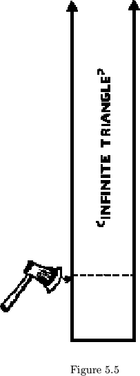
The infinite vertex may as well be chopped off so as to leave each
leaf square, as in figure 5.5. In building flexagons like this out of
squares, one must remember that one edge of each square leaf is theoretically
a cutting off, and cannot be used for a hinge.
When an infinite vertex tries to come to the center of the flexagon,
its parallel hinges will prevent it. It will form instead an infinitely
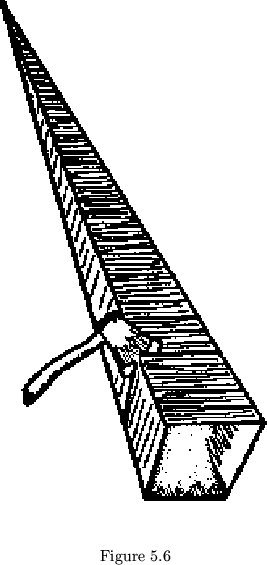
long cylinder, or, in the case of our 2-unit flexagon made of squares, an
open-ended cube (see figure 5.6). Needless to say, such faces will not
``push through'', or reverse inward and outward sides. Other faces of such
a flexagon will appear as in figure 5.7.
There is no reason to stop at zero. Leaves with negative angles
(duly chopped off) are completely acceptable, although the flexagons they
make may at first seem confusing. These flexagons will actually be made
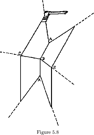
from trapezoidal leaves. When the negative angle in not toward the center
the flexagon will look like figure 5.8, and when the negative angle in
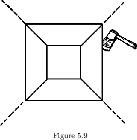
``toward the center'', it will actually be pointing away. In fact, since
it points away, the flexagon may be made to lie flat, upside down, during
such faces, as in figure 5.9. Thus these faces can be ``pushed through''.
A little experimentation will show how this can be the case, improbable as
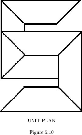
it sounds. An interesting example is the regular flexagon of order 6,
built from the leaves in the unit plan shown in figure 5.10. It must be
remembered, in flexing such a flexagon, that, when the negative angle is
``toward the center'', the flexagon is upside down: the ``upper'' side shows
underneath, the ``lower'' one on the top of the flexagon. Still, in flexing,
the ``lower'' side must be folded together, so that the ``upper'' side will
remain during the next face; i.e., we must flex backwards.
It will be noted in some faces of this flexagon, as in all flexagons
with more than 360 about the center, that these faces are rotated only
with difficulty, and could not be rotated if made of rigid leaves. Thus,
to rotate the hinges
  of the face shown in figure 5.8 to the high
position of hinges
  , the leaves must be bent considerably.
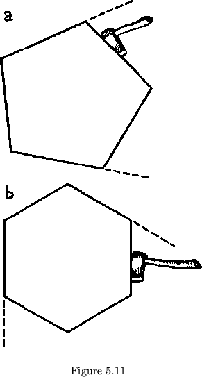
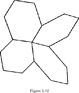
It is not hard to see how leaves with negative angles could be chopped
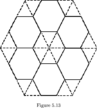
up into pentagons, hexagons, and so forth (see figures 5.11 and 5.12). We
have already used hexagonal leaves, made by cutting off corners of
triangular leaves (see fig. 5-13). Thus we have already begun to relax
the restriction of leaf shapes to triangles. However, so far neither
the pat theory definitions, the map, the tree, nor the triangle network
has needed alteration. Only the original descriptive definition, ``flexible
hexagon'', needs changing. Now that we have seen how polygons of all kinds
can be used to build flexagons, we will break the last remaining restriction
in this direction, by allowing the polygons to have hinges on more
than 3 sides. Doing this will give us another larger field of flexagons
in which, at last, not only will leaves not necessarily be triangular,
but map polygons will not necessarily be triangular, and neither will hinge
network polygons. Moreover, flexagons will not necessarily be pairs of
pats, as heretofore defined.


Next: G-Flexagons
Up: Flexagon
Previous: The Pat Structure
Contents
Pedro
2001-08-22


