 |
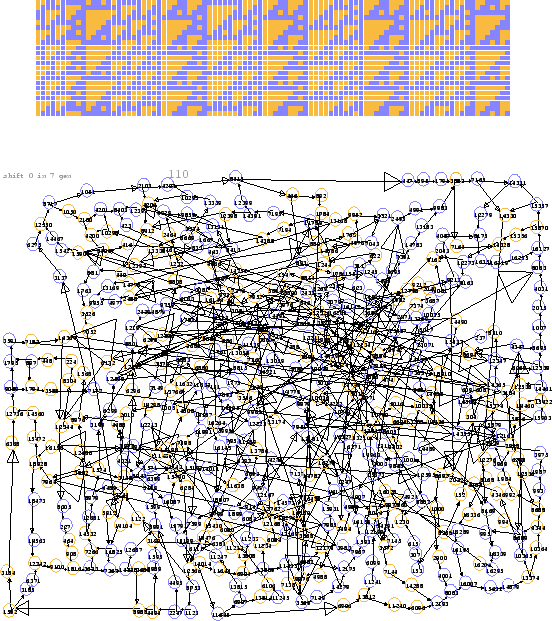
C gliders can occupy a split configuration space, in which the right half is the quiescent zero. That makes the zero vertex an absorbing ideal in the de Bruijn diagram, with its 556 vertices and 705 links. This huge population congests the diagram beyond what will fit nicely on a letter sized page, but removing the zero vertex and all the transients thereby created only reduces the load by about 10%, to 502 nodes and 632 links. No improvement is to be disparaged, however.
The main thing is that the C's pack densely, just like sardines. Basically they are T6's, but a T3 and 3 T1's can be nestled in to get a columnar arrangement of cycle 9. As remarked in Cook's Rule 110 document, there are three different membrane-shift points allowing vertical displacement between successive vertical columns.
As a result the de Bruijn diagram has some cycle-9 loops, although not all of them have been spotted yet. But given that there are seven distinct rows in a C, there ought to be seven of these loops visible in the diagram, the more so because this seems to be the shortest loop present.
There ought to be seven cycle-14 loops as well, containing the unit cells of the pure ether, but they haven't been located, either. On the other hand, since all the nodes have been positioned by hand, it seems certain that the diagram consists of a single component. That does not exclude something communicating just with the zero ideal but not with the nucleus shown in Figure 2.24.
On the other hand, there are readily visible cycles of length 11 sharing part of their arc with cycles of length 20, and there is also a loop of length 17.
What is happening is similar to the layout already apparent for the A and B gliders. Namely, there are some composites which have a shorter cycle length than the full periodicity of the raw ether. The A diagram, for example has a long loop of length 14 which can be taken as the circumference of a big circle, within which there are shorter loops, possibly sharing circumference, which correspond to ether-glider doublets. There is even a short cycle, sharing circumference with others, generating the T1 lattice of ``pure glider.''
In the case of the C's, examination of the cycles shows that they correspond to polymers. This isn't like trees, for which there are polar coordinates and a rather satisfactory diagram can be generated automatically. No doubt, given the interest there is in drawing graphs, there are more suitable programs available, but they haven't been used in this presentation.
 |