


Next: cycle, or basin, diagrams
Up: General properties of Rule 110
Previous: interpretation of graphs
Contents
Underlying the existence of the tiling is the fact that Rule 110 has semipermeable membranes. That is just a fancy way of saying that the sequence x10 always generates 1 (almost always - the ``semi'' comes from 111  0); more pertinent is that
  generates
  which is another way of characterizing the triangles. Membranes are traceable to configurations in the de Bruijn diagram. It remains to be seen how directly this membrane affects the analysis of Rule 110, even though it is an integral part of the characterization of Rule 110 by tiling.
The reason for mentioning this is that it has been known that some rules have membranes bounding macrocells, within which evolution has to seek a cycle. But not all membranes are permanent, leading to the conjecture that their dissolution might be programmed. This is an idea which has probably never been followed up, but Rule 110 may actually be an instance which fits the pattern, since the evolution depends to a certain extent on the persistence of the left margin of the triangles, and the way in which it eventually breaks up.
In honor of the role of C gliders in Cook's introduction, the dimensions of the arrays in NXLCAU21 was raised to accomodate seven generations, with the result that they are described in a diagram of 556 nodes and 705 links. It is large for the multiplicity of ways the ether background can join to the T6's which in turn join to ether or vanish. To better manage the diagram, the self-node to the quiescent state can be excised, leaving a diagram of 502 nodes and 632 links; although only a 10% reduction, it takes away lots of stray lines from a map which is still extremely congested.
Table 1.2 summarizes the statistics on all the de Bruijn diagrams up to and including seven generations. The first row of each pair states the number of nodes, the second row, the number of links. When the two numbers coincide the diagram consists exclusively of loops, but not necessarily one single loop. Since zero is a quiescent state, entries of the form (1,1) indicate that it is the only configuration meeting the shifting requirement. In particular, there are no still lifes (except for zero).
The columns follow the degree of shifting, the remainder, pairs of rows, goes by generation.
Table 1.2:
The number of nodes (upper number) and links (lower number) in the de Bruijn shift diagrams up to and including seven generations.
5 pt
| -7 |
-6 |
-5 |
-4 |
-3 |
-2 |
-1 |
0 |
1 |
2 |
3 |
4 |
5 |
6 |
7 |
| 85 |
46 |
26 |
15 |
9 |
5 |
1 |
1 |
1 |
5 |
10 |
19 |
34 |
60 |
106 |
| 85 |
46 |
26 |
15 |
9 |
5 |
1 |
1 |
1 |
5 |
10 |
19 |
34 |
60 |
106 |
| 42 |
31 |
22 |
19 |
10 |
1 |
1 |
9 |
1 |
9 |
15 |
5 |
33 |
24 |
90 |
| 42 |
31 |
22 |
19 |
10 |
1 |
1 |
11 |
1 |
9 |
15 |
5 |
33 |
24 |
90 |
| 75 |
23 |
38 |
19 |
1 |
5 |
9 |
19 |
1 |
27 |
22 |
37 |
42 |
5 |
134 |
| 75 |
23 |
38 |
19 |
1 |
5 |
9 |
22 |
1 |
35 |
22 |
37 |
42 |
5 |
134 |
| 42 |
68 |
26 |
13 |
1 |
41 |
15 |
17 |
1 |
1 |
10 |
13 |
26 |
47 |
109 |
| 42 |
68 |
26 |
13 |
1 |
49 |
15 |
19 |
1 |
1 |
10 |
13 |
26 |
47 |
109 |
| 110 |
19 |
1 |
23 |
10 |
58 |
1 |
86 |
9 |
116 |
42 |
38 |
66 |
14 |
161 |
| 110 |
19 |
1 |
23 |
10 |
63 |
1 |
102 |
9 |
142 |
42 |
38 |
66 |
14 |
161 |
| 85 |
31 |
94 |
99 |
1 |
27 |
100 |
57 |
1 |
15 |
1 |
126 |
26 |
48 |
85 |
| 85 |
31 |
100 |
111 |
1 |
27 |
112 |
62 |
1 |
15 |
1 |
164 |
26 |
48 |
85 |
| 14 |
219 |
9 |
129 |
1 |
266 |
1 |
556 |
1 |
5 |
18 |
1 |
69 |
5 |
169 |
| 14 |
239 |
9 |
136 |
1 |
287 |
1 |
705 |
1 |
5 |
18 |
1 |
69 |
5 |
169 |
|
Points of interest in the table, actually some of Cook's gliders, are the entries at (2,3) [A-gliders], at (-2.4) [B-gliders], and at (0,7) [C-gliders]. [The symbol (x,y) indicates a shift of x, negative to the left, in y generations].
Previously unreported gliders can be found at (2,5), (-1,6), and (-4,6). The (2,5) glider had already been observed in Cook's extensible gliders, but none of the three connects directly to Cook's ether.
Figure 1.19:
Inventory of left shifting configurations. The quiescent configuration is an implicit component of every other shift; sometimes it is the only one. Otherwise it is not shown. When there are still more components, the panel is split into horizontal slices to accomodate them.
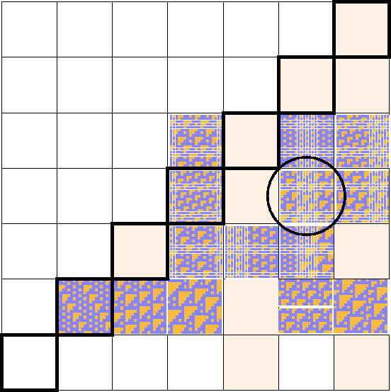 |
Figure 1.20:
Periodic configurations. The quiescent configuration is an implicit component of every other shift; sometimes it is the only one. Otherwise it is not shown. When there are still more components, the panel is split into horizontal slices to accomodate them. That is not the same as a one-sided ideal, in which one single panel divides into two distinctive regions along a vertical fissure.
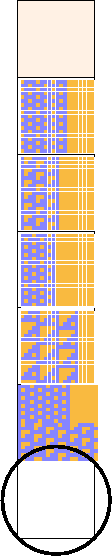 |
Figure 1.21:
Inventory of right shifting configurations. The horizontal coordinate determines the shift, the vertical coordinate the number of generations which have elapsed. The quiescent configuration is an implicit component of every other shift; sometimes it is the only one. Otherwise it is not shown.
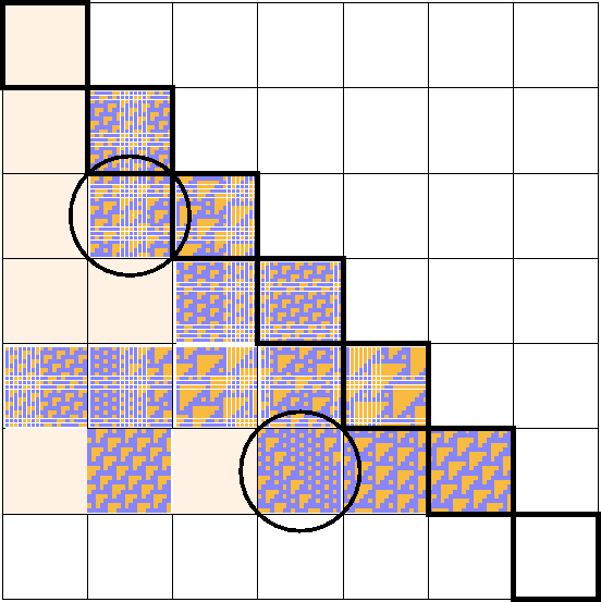 |
Table 1.3:
The number of nodes and links in the de Bruijn
shift diagrams for eight generations.
5 pt
| Shift |
nodes |
links |
cycles |
comments |
| --- |
--- |
--- |
------ |
----- |
| left 8 |
93 |
93 |
1, 4, 8, 90 |
|
| left 7 |
56 |
56 |
1, 55 |
|
| left 6 |
35 |
35 |
1, 34 |
|
| |
|
|
|
|
| left 5 |
182 |
193 |
2 components |
Zero, and two big crosslinked cycles
involving T7's. The interlinking makes
for two packings, so a glider pairing
could be imagined, as in some of the
combinations seen previously. |
| |
|
|
|
|
| left 4 |
381 |
447 |
doubled B's |
The velocity is the same as for B
gliders, with double the time available
to complete the shift. The (-2)/4 B
configuration must be a subset; it is
an absorbing ideal paired with a T5
combination in an emitting ideal. This
is a fuse, not gliders, and the figures
move parallel to one another. |
| left 3 |
10 |
10 |
1, 9 |
|
| left 2 |
37 |
37 |
1, 2x7, 22 |
|
| left 1 |
38 |
38 |
1, 37 |
|
| |
|
|
|
|
| static |
41 |
43 |
2 components |
T1 emitting ideal connects to zero as
an absorbing ideal in a diagram with
33 nodes, 35 links. An independent
cycle length 8 contains a T2 mosaic. |
| right 1 |
22 |
22 |
1, 21 |
|
| right 2 |
1 |
1 |
1 |
|
| right 3 |
1 |
1 |
1 |
|
| |
|
|
|
|
| right 4 |
145 |
153 |
4 components |
1) Quiescent zero configuration
2) T5's over T1's, in 2 phases
3) T1 emitting ideal connects to 4
different absorbing ideals, phases of
T3's over T1's, which might be seen as
some staggered B gliders. |
| right 5 |
208 |
208 |
1, 2x7, 193 |
|
| right 6 |
152 |
152 |
various hashes |
|
| |
|
|
|
|
| right 7 |
301 |
301 |
several |
a variety of cycles, some of them
rather pretty. |
| right 8 |
13 |
13 |
1, 4, 8 |
|
|
Table 1.4:
The number of nodes and links in the
de Bruijn left shift diagrams for nine generations.
5 pt
| Shift |
nodes |
links |
cycles |
comments |
| --- |
--- |
--- |
------ |
----- |
| |
|
|
|
|
| left 9 |
10 |
10 |
1, 9 |
Zero, T2's stacked vertically |
| |
|
|
|
|
| left 8 |
57 |
57 |
1, 4x14 |
This combination is important because
it is one of the two in the ninth
generation in which the crystallography
of the ether tiles allows gliders. We
see the zero configuration and four of
spatial period (cycle) 14, of which
one is the ether lattice and the other
three phases of a salvo of fat A
gliders with seven T1's, even though
they conform to a left-moving
displacement criterion. Since only
the one combination is allowed and
there are no alternatives, this mixture
might not be a glider even though it
has the appearance of one. |
| |
|
|
|
|
| left 7 |
1 |
1 |
1 |
only the quiescent configuration |
| left 6 |
59 |
59 |
1, 3x12, 3x6, 4 |
|
| left 5 |
26 |
26 |
1, 25 |
|
| |
|
|
|
|
| left 4 |
216 |
225 |
fuse |
4-high A's defer to diagonally
stacked T8's. |
| left 3 |
9 |
9 |
1, 8 |
|
| |
|
|
|
|
| left 2 |
370 |
406 |
1, fuse |
Zero, and a component in which T1's
form the emitting ideal, a combination
of T8, T3, and 3 T1's repeat to
constitute the absorbing ideal. |
| |
|
|
|
|
| left 1 |
587 |
666 |
1, mixed |
A combination of T8, T3, and two T1's
remimiscent of the C glider; they can
waver in their vertical alignment in
a way which could be construed as
forming a glider family. |
|
Table 1.5:
The number of nodes and links in the
de Bruijn static and right shift diagrams for nine generations.
5 pt
| Shift |
nodes |
links |
cycles |
comments |
| --- |
--- |
--- |
------ |
----- |
| |
|
|
|
|
| static |
689 |
771 |
big diagram |
Includes the T2 emitter, Zero absorber
visible in the third generation as one
component, There is also a glider
bombardment of a T5 wall, and the T5
wall as a source of B glider salvos
which annihilate an oncoming A salvo.
This is a ``black hole'' configuration
which often forms from two oppositely
directed shift configurations. The T5's
form an absorbing ideal which contains
one of the two allotropic forms
of the gliders previously found in the
``four left in six generations''
analysis. |
| right 1 |
1 |
1 |
1 |
|
| right 2 |
5 |
5 |
1, 4 |
|
| right 3 |
1 |
1 |
1 |
|
| right 4 |
1 |
1 |
1 |
|
| right 5 |
34 |
34 |
1, 8, 25 |
|
| |
|
|
|
|
| right 6 |
604 |
784 |
1, A's |
Zero, all kinds of A's but nothing
evident which was not already visible
with the ``2 left every 3'' row, so
there are neither double nor triple
A-bar's. This is the other shift
combination for which the ether
lattice could have had ninth
generation gliders. |
| right 7 |
125 |
125 |
1, 124 |
|
| right 8 |
51 |
51 |
1, 50 |
|
| right 9 |
94 |
94 |
1, 9, 21, 63 |
|
|
Next: cycle, or basin, diagrams
Up: General properties of Rule 110
Previous: interpretation of graphs
Contents
Jose Manuel Gomez Soto
2002-01-31