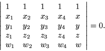
The representation of functions of three variables through contours in a space of three dimensions follows the same lines that have already been discussed, once the dimension of the pertinent sets of basis monomials has been taken into account. Thus four monomials,
![]() are required in three dimensions, with the basic equation taking the form of a
are required in three dimensions, with the basic equation taking the form of a
![]() Vandermonde determinant
Vandermonde determinant

Not only does every increase in dimension make a symbolic solution of this equation less tractable, the problems of graphical representation become increasingly more difficult. If we would represent segments of two dimensional contours by line segments, we should represent segments of three dimensional contours by fragments of planes, which is a much more complicated process; we would probably represent such a fragment by a set of lines, such as those forming the border where it intersects the coordinate grid.
As always, the question of where the data points lie with respect to the coordinate grid arises; not all four points should lie on the same face of a cube, to avoid linear dependencies in the Vandermonde matrix.
The coordinate cubes have eight vertices, which is double the required number of points. One solution is to decompose the cube into six tetrahedra just as the coordinate square was decomposed into two triangles in two dimensions. Even though the work is multiplied by six, the greater part of the classification into cases according to how the contour surfaces cross the edges and faces of the cube is eliminated.
Generally the intersection of a plane with a tetrahedron is a triangle, but it has to be remembered that quadrilateral sections are also possible--for example when the interecting plane is parallel or nearly parallel to a pair of opposite edges of the tetrahedron.
Other approaches are possible if it is not required that the contour planes be represented by lines passing through the grid lines. For example, a circle could be traced out tangent to the grid lines, so that its counterimage on the contour plane could be plotted. The result would be a network of tangent ellipses which might cover the contour surface fairly well.
Determining the parameters of circles and calculating their points--even by table lookup--would consume additional time; a simpler approach would to be to trace the counterprojection of the edge-dual network formed from the coordinate grid. This network would consist of lines joining the midpoints of the edges of the faces of the coordinate cubes.
Of course this discussion makes no mention at all of visibility. Nothing need be said if a simple wire frame model is all that is desired. But, if the surface is assumed to be opaque or semitransparent, it is inevitable that some parts of it would be obscured by others. Then, further calculations would be required to decide whether, or how much, of the surface patches would be visible.