Each and every ![]() cut is characterized by the presence of a single
leaf or sub-pat in one of the two pats. This single sub-pat will have a
hinge difference across it equal to the order of the
cut is characterized by the presence of a single
leaf or sub-pat in one of the two pats. This single sub-pat will have a
hinge difference across it equal to the order of the ![]() cut flex, be it a
cut flex, be it a
![]() flex or a tubulation, since the order of a flex is defined as being
equal to the value of the hinge difference across any pat involved in the
flexing operation. Since in following the
flex or a tubulation, since the order of a flex is defined as being
equal to the value of the hinge difference across any pat involved in the
flexing operation. Since in following the ![]() cut cycle each sub-pat is left
alone in a pat in the order that the sub-pat turns up in the plan, the
plan for one cycle of an improper flexagon may be constructed by following
the
cut cycle each sub-pat is left
alone in a pat in the order that the sub-pat turns up in the plan, the
plan for one cycle of an improper flexagon may be constructed by following
the ![]() cut cycle while noting what order flex is required to reach each
face from the previous one. The results may be checked by orienting
the leaf polygons and noting exactly what the hinge difference across each
single sub-pat really is. Care must be taken, however, that the
orientation is such that a forward
cut cycle while noting what order flex is required to reach each
face from the previous one. The results may be checked by orienting
the leaf polygons and noting exactly what the hinge difference across each
single sub-pat really is. Care must be taken, however, that the
orientation is such that a forward ![]() flex uses a number 1 hinge, not a
flex uses a number 1 hinge, not a
![]() -hinge.
-hinge.
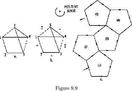
Let us see how this works with the pentaflexagon pictured in figure
9.9. Let us start at face 1-4. The first ![]() cut flex is between side
1 and side 2. This flex removes
all leaves except leaf 1, 2 from the
left hand pat. We note that this is
a
cut flex is between side
1 and side 2. This flex removes
all leaves except leaf 1, 2 from the
left hand pat. We note that this is
a ![]() flex, for it uses hinges which
are in a 1 position, and further,
that the hinge difference across the
single leaf 1, 2 is +1. The next
flex, for it uses hinges which
are in a 1 position, and further,
that the hinge difference across the
single leaf 1, 2 is +1. The next ![]() cut
flex is from 2 to 3. This also is a
cut
flex is from 2 to 3. This also is a ![]() flex, and we note that leaf 2, 3
has a hinge difference across it of +1. The
flex, and we note that leaf 2, 3
has a hinge difference across it of +1. The ![]() cut between 3 and 4 is
a tubulation with flex value of 2. Leaf 3, 4 has a hinge value of +2.
To reach side 5, we must back flex, or
cut between 3 and 4 is
a tubulation with flex value of 2. Leaf 3, 4 has a hinge value of +2.
To reach side 5, we must back flex, or ![]() flex (
flex (![]() flex). Leaf 4, 5
is -1 (but note that side 5 faces away). From here, we may
flex). Leaf 4, 5
is -1 (but note that side 5 faces away). From here, we may ![]() flex to
1, noting that leaf 5, 1 is +2. From this information we may obtain the
number and sign sequences, and then the plan:
flex to
1, noting that leaf 5, 1 is +2. From this information we may obtain the
number and sign sequences, and then the plan:
| +1 | +1 | +2 | -1 | +2 |
| (1) | 3 | (3) | 5 | 5 |
| 2 | (2) | 4 | (4) | 1 |
It should be noted that before proceeding with the determination of the plan,
it was necessary first to decide which way around the ![]() cut cycle we were
to travel, and second, just how to orient the leaf polygon. The orientation
was determined by choosing arbitrarily a forward
cut cycle we were
to travel, and second, just how to orient the leaf polygon. The orientation
was determined by choosing arbitrarily a forward ![]() flex and assigning to
it a positive sense. This may be represented on the map as in figure
9.9b. In such a flexagon, any flex represented by a solid vector is a
flex and assigning to
it a positive sense. This may be represented on the map as in figure
9.9b. In such a flexagon, any flex represented by a solid vector is a
![]() flex. If the path is traversed in reverse, that is, against the vector, a
flex. If the path is traversed in reverse, that is, against the vector, a
![]() hinge is required. Thus, although traveling from 5 to 4 requires
a
hinge is required. Thus, although traveling from 5 to 4 requires
a ![]() flex, traveling from 4 to 5 requires a
flex, traveling from 4 to 5 requires a ![]() flex or a
flex or a ![]() flex. Here,
then, is a method for determining the signs for the hinge differences
across all leaves with a +1 or
flex. Here,
then, is a method for determining the signs for the hinge differences
across all leaves with a +1 or ![]() hinge: A direction about the map is
designated as +, and one of the
hinge: A direction about the map is
designated as +, and one of the ![]() cut
cut ![]() flexes is assigned a vector in
this + direction. The
flexes is assigned a vector in
this + direction. The ![]() flex cycle is then followed, and vectors are
drawn on all lines so that one vector enters and one vector leaves every
vertex of the map polygon. Those
flex cycle is then followed, and vectors are
drawn on all lines so that one vector enters and one vector leaves every
vertex of the map polygon. Those ![]() flex vectors that are of the
flex vectors that are of the ![]() cut cycle
may be given +1 or
cut cycle
may be given +1 or ![]() values depending on whether they point with or
against the preassigned + direction. If the values of any tubulations
on the
values depending on whether they point with or
against the preassigned + direction. If the values of any tubulations
on the ![]() cut cycle are known, they may also be assigned vectors in
accordance with their + or
cut cycle are known, they may also be assigned vectors in
accordance with their + or ![]() sense (see figure 9.9b). It should be noted
that a
sense (see figure 9.9b). It should be noted
that a ![]() flex is congruent to a
flex is congruent to a ![]() flex mod.
flex mod. ![]() .
.
Here we have the true meaning of the polygon system. For any given
proper flexagon, the orientation of the map polygon is opposite for
adjacent cycles, and thus the signs in the plan are reversed. The
convenience of turning in a + or ![]() direction when traveling around the map
polygons works with proper flexagons but not with improper ones, in which
signs other than
direction when traveling around the map
polygons works with proper flexagons but not with improper ones, in which
signs other than ![]() are used.
are used.
With the knowledge we now have we may find the plan of any given
proper and many of the improper tetraflexagons. By assigning a positive
direction and by fixing one vector, all of the other ![]() cut flexes may be
given a direction for any proper tetraflexagon and for any improper
tetraflexagon, in which each cycle has only
cut flexes may be
given a direction for any proper tetraflexagon and for any improper
tetraflexagon, in which each cycle has only ![]() flexes in common with the
neighboring cycles (those flexagons in which the cycles are attached by
tubulations will be discussed later). All tubulations in tetraflexagons and
pentaflexagons will signify hinge differences of +2 or -2, but in all
tetraflexagons these are indistinguishable as far as the plan is concerned. Thus,
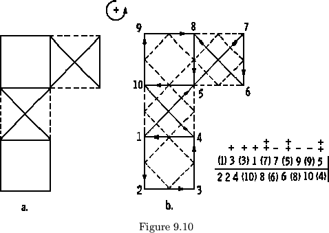
given a tetraflexagon as shown in figure 9.10a, we assign a + direction
(counterclockwise),
draw vectors, and then construct the polygon system (see figure 9.10b.). As
the polygon system touches each path in turn,
we look at the type of flex; if it is a tubulation
(
flexes in common with the
neighboring cycles (those flexagons in which the cycles are attached by
tubulations will be discussed later). All tubulations in tetraflexagons and
pentaflexagons will signify hinge differences of +2 or -2, but in all
tetraflexagons these are indistinguishable as far as the plan is concerned. Thus,
given a tetraflexagon as shown in figure 9.10a, we assign a + direction
(counterclockwise),
draw vectors, and then construct the polygon system (see figure 9.10b.). As
the polygon system touches each path in turn,
we look at the type of flex; if it is a tubulation
(![]() flex) we can simply write
flex) we can simply write ![]() (+2),
whereas if it is a
(+2),
whereas if it is a ![]() flex we compare the
vector with the preassigned positive direction.
If the vector goes with the + direction the
vector is +1 and if it goes against the + direction
the vector is
flex we compare the
vector with the preassigned positive direction.
If the vector goes with the + direction the
vector is +1 and if it goes against the + direction
the vector is ![]() . In improper flexagons with cycles
higher than four we have a problem, for we have no way of reading the value
of the tubulations in the
. In improper flexagons with cycles
higher than four we have a problem, for we have no way of reading the value
of the tubulations in the ![]() cut cycle nor can we tell the sign associated with
the tubulation at a glance, directly from the map.
In order to calculate the value of the
tubulations, we must employ a new principle. This principle states that the
sum of the hinge differences encountered in flexing from a given point to another
given point is constant regardless of the paths followed. To demonstrate this let
us look again at the flexagon in figure 9.9. If we are at side 3 with 2 on the
back and we want to flex to side 5, there are a number of paths we can use.
Let us consider the two paths
cut cycle nor can we tell the sign associated with
the tubulation at a glance, directly from the map.
In order to calculate the value of the
tubulations, we must employ a new principle. This principle states that the
sum of the hinge differences encountered in flexing from a given point to another
given point is constant regardless of the paths followed. To demonstrate this let
us look again at the flexagon in figure 9.9. If we are at side 3 with 2 on the
back and we want to flex to side 5, there are a number of paths we can use.
Let us consider the two paths ![]() and
and ![]() . If we
. If we ![]() flex from 3 to 5
and don't rotate, we find that the hinge difference associated with the
flex is +1 and that this hinge difference is arrived at by
adding the hinge differences in the leaves which comprise the left pat. It
is the hinge difference across these two leaves in which we are interested.
This hinge difference, being +1 means that the hinge difference across the
leaf 3,4 plus that across 4,5 must be equal to +1. In this case
flex from 3 to 5
and don't rotate, we find that the hinge difference associated with the
flex is +1 and that this hinge difference is arrived at by
adding the hinge differences in the leaves which comprise the left pat. It
is the hinge difference across these two leaves in which we are interested.
This hinge difference, being +1 means that the hinge difference across the
leaf 3,4 plus that across 4,5 must be equal to +1. In this case ![]() and
and
![]() and the sum is +1. Now if we go to side 5 by the paths
and the sum is +1. Now if we go to side 5 by the paths ![]() , we
would expect to first encounter a hinge difference across leaf 3,4 and then
a hinge difference across leaf 4,5. Since these
are unchanged for a single leaf, we would expect to encounter first a +2
flex and then a
, we
would expect to first encounter a hinge difference across leaf 3,4 and then
a hinge difference across leaf 4,5. Since these
are unchanged for a single leaf, we would expect to encounter first a +2
flex and then a ![]() flex. The sum of these two flexes is +1, as predicted.
flex. The sum of these two flexes is +1, as predicted.
In general, if a shortcut flex between two sides removes all but ![]() leaves
from one of the pats, then in traversing the
leaves
from one of the pats, then in traversing the ![]() cut cycle between
these two sides, each one of the
cut cycle between
these two sides, each one of the ![]() leaves must take a turn at being the
only leaf in a pat. Since the hinge difference across the entire degree
leaves must take a turn at being the
only leaf in a pat. Since the hinge difference across the entire degree
![]() pat is equal to the sum of the hinge differences of each leaf in the pat,
this sum must equal the sum of the hinge differences of the operations
encountered in the
pat is equal to the sum of the hinge differences of each leaf in the pat,
this sum must equal the sum of the hinge differences of the operations
encountered in the ![]() cut cycle.
cut cycle.
Now we have a valuable tool with which we can determine the nature of
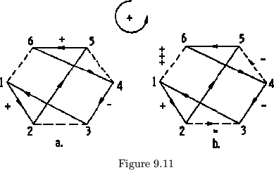
any tubulation we wish to. In a given map such as the one in figure 9.11,
we may orient all the ![]() flexes and assign a positive direction. All
flexes and assign a positive direction. All
![]() flexes on the
flexes on the ![]() cut cycle should be assigned + or - values according
to whether their vectors go with
or against the positive direction.
Each
cut cycle should be assigned + or - values according
to whether their vectors go with
or against the positive direction.
Each ![]() cut greater-than-1-flex
may be assigned values by finding
another path consisting of 1-flexes
by which the gap across the tubulation
may be bridged. In figure 9.11a, side
2 may be reached from side 3 either by the tubulation 3-2 or by the
sequence of 1-flexes 3, 1, 2. If this 1-flex path goes with the vectors
drawn on the map, the hinge difference for each 1-flex is +1; if it goes
against the vector, the hinge difference is -1. The hinge differences
for all the 1-flexes are then added up and the sum is equal to the hinge
difference across the tubulation. Care must be taken with the direction
of traversing the tubulation. In our example, the 3-2 flex is in a
negative direction, and since it is equal to the two +1-flexes, 3-1 and 1-2,
the value of the tubulations is -2. The other tubulations are handled
similarly. (see figure 9.11b). Now with all of the values known for the
cut greater-than-1-flex
may be assigned values by finding
another path consisting of 1-flexes
by which the gap across the tubulation
may be bridged. In figure 9.11a, side
2 may be reached from side 3 either by the tubulation 3-2 or by the
sequence of 1-flexes 3, 1, 2. If this 1-flex path goes with the vectors
drawn on the map, the hinge difference for each 1-flex is +1; if it goes
against the vector, the hinge difference is -1. The hinge differences
for all the 1-flexes are then added up and the sum is equal to the hinge
difference across the tubulation. Care must be taken with the direction
of traversing the tubulation. In our example, the 3-2 flex is in a
negative direction, and since it is equal to the two +1-flexes, 3-1 and 1-2,
the value of the tubulations is -2. The other tubulations are handled
similarly. (see figure 9.11b). Now with all of the values known for the
![]() cut cycle, the polygon network can be drawn, and as the network touches
each face in turn, the hinge value is recorded as being identified with
that particular point.
cut cycle, the polygon network can be drawn, and as the network touches
each face in turn, the hinge value is recorded as being identified with
that particular point.
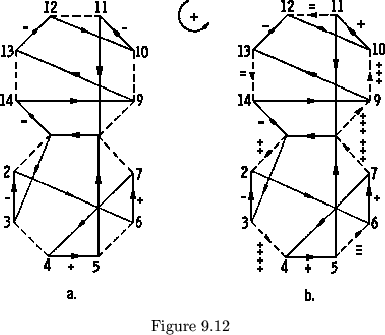
Example:
To find the plan of the octaflexagon pictured in figure 9.12, we will arbitrarily orient the 1-flexes by drawing vectors as in the figure, and we will arbitrarily assign counterclockwise a positive sense. Now we must look at each 0-cut 1-flex and discover whether it goes with or against this arbitrary positive sense. When the sign of these 1-flexes is being determined, the 1-flex in question must be referred to the map as a whole; not to the individual cycle of which that 1-flex is a part. The 1-flex values for this map are as follows:
| 3-2 | -1 | 10-11 | +1 | |
| 4-5 | +1 | 13-12 | -1 | |
| 6-7 | +1 | 1-14 | -1 |
Now we tackle the 0-cut tubulations. First let us consider the
tubulation from 1 to 2. There are two possible 1-flex sequences to travel
from 1 to 2: 1, 3, 2 and 1, 8, 5, 4, 7, 6, 2. In the first sequence, the flexing
proceeds in the direction of the preassigned vectors, so all 1-flexes are
positive. There are two such 1-flexes, 1-3 and 3-2, so since the hinge
difference across the tubulation must equal the sum of the hinge differences
of the 1-flexes encountered, the flex 1-2 is a 2-flex. Furthermore,
since the vector 1-2 is in a counterclockwise direction, the
tubulation is a +2-flex when traversing the ![]() cut cycle in the assigned
positive (counterclockwise) sense. In the second sequence
cut cycle in the assigned
positive (counterclockwise) sense. In the second sequence
![]() ,
the direction of flexing is against the vectors, so the flexes are
,
the direction of flexing is against the vectors, so the flexes are ![]() flexes. By this scheme, the flex 1-2 is a
flexes. By this scheme, the flex 1-2 is a ![]() flex. This, however, is
identical with the results obtained from the first sequence, for a
flex. This, however, is
identical with the results obtained from the first sequence, for a
![]() flex is identical with a
flex is identical with a ![]() flex.
flex.
All the rest of the 0-cut tubulations may be evaluated in the above manner. Following is a chart of the results obtained:
| 0-cut | Shortcut | Hinge | Sense of | 0-cut |
| flex | sequence | value | Tubulation | value |
| 3-4 | 3,2,6,7,4 | +4 | + | +4 |
| 5-6 | 5,4,7,6 | -3 | + | -3 |
| 7-8 | 7,4,5,8 | +3 | + | +3 |
| 8-9 | 8,1,14,9 | +3 | + | +3 |
| 10-9 | 10,12,13,9 | -3 | - | -3 |
| 12-11 | 12,10,11 | +2 | - | -2 |
| 14-13 | 9,13 | +2 | - | -2 |
The first column specifies the tubulation under consideration and the direction the flex is to proceed (thus 3-4 signifies the flex from 3 to 4). The second column designates the sequence of shortcut flexes used to avoid the tubulation. The third column tells the sum of the hinge values of the shortcut flexes. The sum is positive if the flexing proceeds with the preassigned vectors and negative if against them. The fourth column tells whether the direction in which the 0-cut flex was effected was with (+) or against (-) the assigned positive sense. The last column gives the final hinge value for the 0-cut flex if flexing were proceeding in a consistently positive direction along the 0-cut cycle. Now, with the value of each 0-cut flex known, the polygon network may be drawn and followed. As each face is visited in turn, its constant order number and hinge value may be noted down. The plan may be constructed with this information:
|
|
- |
|
+ |
|
+ |
|
- |
|
- | |
+ |
|
|
||||||||||||||||
| (1) | 3 | (3) | 5 | (5) | 7 | (7) | 1 | (13) | 13 | (11) | 11 | (9) | 7 | ||||||||||||||||
| 2 | (2) | 4 | (4) | 6 | (6) | 8 | (14) | 14 | (12) | (10) | 10 | (8) | 8 |
Each operation shown by the map may now be given flex values by this
same method. To find the value of a tubulation from any side ![]() to any side
to any side
![]() in a given cycle all we have to do is add up the value of the flexes along
a 0-cut cycle from
in a given cycle all we have to do is add up the value of the flexes along
a 0-cut cycle from ![]() to
to ![]() . Thus the value of the tubulation from 1 to
4 in figure 9.11b is
. Thus the value of the tubulation from 1 to
4 in figure 9.11b is
![]() . To do this systematically for every
path on the map we write all the 0-cut values for each side in order. Then
we systematically iterate all possible paths on the map. In the case of the
flexagon in figure 9.11 these possibilities are 1-2, 1-3, 1-4, 1-5, 1-6,
2-3, 2-4, 2-5, 2-6, 3-4, 3-5, 3-6,
4-5, 4-6 and 5-6. The value of the
path 1-2 is found by looking at the
hinge difference between 1 and 2; that
of path 1-3 by adding the hinge
difference of 1-2 to the hinge difference
of 2-3, that of 1-4 by adding
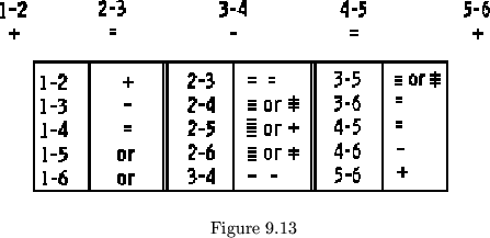
1-2, 2-3, and 3-4, etc. (see figure 9.13). In the manner above described
it is possible to build and predict the properties of any proper or
improper flexagon we have so far considered.
. To do this systematically for every
path on the map we write all the 0-cut values for each side in order. Then
we systematically iterate all possible paths on the map. In the case of the
flexagon in figure 9.11 these possibilities are 1-2, 1-3, 1-4, 1-5, 1-6,
2-3, 2-4, 2-5, 2-6, 3-4, 3-5, 3-6,
4-5, 4-6 and 5-6. The value of the
path 1-2 is found by looking at the
hinge difference between 1 and 2; that
of path 1-3 by adding the hinge
difference of 1-2 to the hinge difference
of 2-3, that of 1-4 by adding
1-2, 2-3, and 3-4, etc. (see figure 9.13). In the manner above described
it is possible to build and predict the properties of any proper or
improper flexagon we have so far considered.
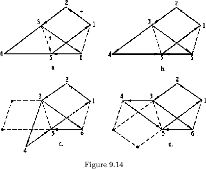
Now, at last, it is possible to see why there are two possible ways of
attaching two given improper cycles by any two given 0-cut tubulations of the
same order. Let us go back to the flexagons in figure 9.6b. The right hand
cycle may be determined by arbitrarily assigning a + direction and 1-flex
vector (see figure 9.14a). The tubulation in common with the two cycles is
then determined as
![]() when going from 3 to 5. This tubulation then determines the
two 1-flexes of the second cycle which also bridge the gap between 3 and 5.
If in traveling across from 3 to 5 the tubulation
is
when going from 3 to 5. This tubulation then determines the
two 1-flexes of the second cycle which also bridge the gap between 3 and 5.
If in traveling across from 3 to 5 the tubulation
is ![]() , then in traveling from 3 to 4 to 5 the sum of
the hinge values for those flexes must be +2, or each single flex
must be +1. These flexes may now be given vectors (see figure 9.14b).
When the other two sides are added to complete the new cycle, the two 1-flexes
which bridge the tubulation have a choice as to which position they take (see
figure 9.14 c & d). In both cases, the 1-flex which remains a 0-cut goes in a
positive direction, thus satisfying all requirements. In figuring out the plans
to improper flexagons with cycles attached to the tubulations, one cycle at
a time must be figured out so that the value of the
tubulation in common with two cycles is known
first and can be used to determine the other
cycle. It should be emphasized, however, that
two cycles can only be attached by a flex whose
absolute value is the same for both cycles. Thus
a
, then in traveling from 3 to 4 to 5 the sum of
the hinge values for those flexes must be +2, or each single flex
must be +1. These flexes may now be given vectors (see figure 9.14b).
When the other two sides are added to complete the new cycle, the two 1-flexes
which bridge the tubulation have a choice as to which position they take (see
figure 9.14 c & d). In both cases, the 1-flex which remains a 0-cut goes in a
positive direction, thus satisfying all requirements. In figuring out the plans
to improper flexagons with cycles attached to the tubulations, one cycle at
a time must be figured out so that the value of the
tubulation in common with two cycles is known
first and can be used to determine the other
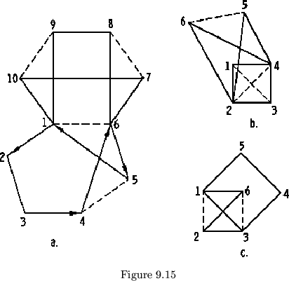
cycle. It should be emphasized, however, that
two cycles can only be attached by a flex whose
absolute value is the same for both cycles. Thus
a ![]() flex in one cycle of a hexaflexagon cannot
be used to attach it to a
flex in one cycle of a hexaflexagon cannot
be used to attach it to a ![]() flex in another (see figure 9.15a).
flex in another (see figure 9.15a).
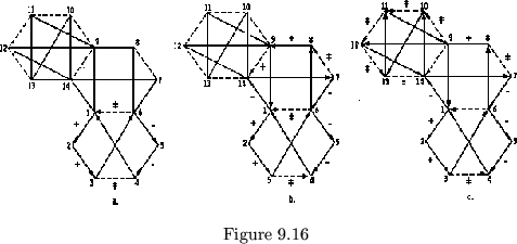
Example:
To find the plan of the hexaflexagon in figure 9.16, we assign a
positive direction, and arbitrarily orient the 1,2,3,6,5,4, cycle, as
in figure 9.16a. The values for the ![]() flexes in this cycle may then
be determined, and from them, the two 0-cut tubulations. The value
of the flex from 6 to 1 may be determined as
flexes in this cycle may then
be determined, and from them, the two 0-cut tubulations. The value
of the flex from 6 to 1 may be determined as
![]() from the 1-flex cycle
6,5,4,1. Now, in the second cycle, the 1-flex cycle 6,8,9,1 also
spans the tubulation. The sum of these three
from the 1-flex cycle
6,5,4,1. Now, in the second cycle, the 1-flex cycle 6,8,9,1 also
spans the tubulation. The sum of these three ![]() flexes must equal
the tubulation value +3. However, either three +1-flexes or three
flexes must equal
the tubulation value +3. However, either three +1-flexes or three
![]() flexes will work since for hexaflexagons a +3-flex is the same as
a
flexes will work since for hexaflexagons a +3-flex is the same as
a ![]() flex. So, we have a choice for orienting the second cycle.
Let us choose the orientation in figure
9.16b. We can now specify values for
all the 0-cut flexes and in particular,
we find that 9 to 14 is a +2-flex.
Since 9-12-14 is the only set of two
flex. So, we have a choice for orienting the second cycle.
Let us choose the orientation in figure
9.16b. We can now specify values for
all the 0-cut flexes and in particular,
we find that 9 to 14 is a +2-flex.
Since 9-12-14 is the only set of two
![]() flexes of the third cycle bridging
this tubulation, they must be +1-flexes,
and again we can determine all the 0-cut flexes. The number and sign
sequences may now be written down:
flexes of the third cycle bridging
this tubulation, they must be +1-flexes,
and again we can determine all the 0-cut flexes. The number and sign
sequences may now be written down:
| + | + |
|
- | - | - |
|
|
|
|
|
+ | |
- | + | |||||||||
| (1) | 3 | (3) | 5 | (5) | 1 | (9) | 11 | (11) | 13 | (13) | 9 | (7) | 7 | (1) | |||||||||
| 2 | (2) | 4 | (4) | 6 | (14) | 10 | (10) | 12 | (12) | 14 | (8) | 8 | (6) | 2 |
