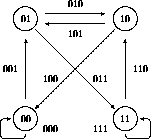
Figure 7: The generic (2,1) de Bruijn diagram.
Through the intermediary of a de Bruijn diagram, graphs can represent configurations, or classes of configurations, in cellular automata. The links of a de Bruijn diagram are naturally associated with the neighborhoods of an automaton using the same symbols, which associates the links with a step of evolution in an equally natural fashion. If there is any reason to discriminate between neighborhoods, the same discrimination may define a subdiagrams of the de Bruijn diagram. A good example of the process arises from the still lifes---configurations of cells which do not change during the course of evolution.
The generic de Bruijn diagram for a (2,1) automaton (one having two states per cell with a single neighbor on each side, according to Stephen Wolfram's notation [9]) has four nodes corresponding to the four two-cell partial neighborhoods, with eight links representing the full three-cell neighborhoods. Such a diagram is shown in Figure 7.

Figure 7: The generic (2,1) de Bruijn diagram.
The still life diagram may be extracted from the generic diagram by removing all links which do not conserve their central cell during the automaton's evolution. Loops in the subdiagram composed of the remaining links define sequences, rather than individual cells, which are invariant to evolution. By reading off such sequences, all the still lifes for the automaton are automatically determined.
In general any boolean combination of the cells of the neighborhood and the evolved cell may determine the subdiagram, leading to chains of cells all of which fulfill the same property. As an example, one important binary automaton evolves according to the so-called Rule 22 [9]:
.1em
![]()
The de Bruijn diagram has eight links connecting four nodes (namely, 00, 01, 10, and 11); keep or reject the links according to whether they conserve their central cell, with results summarized by the following table:
.1em
![]()

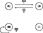
Figure 8: Subdiagram generated by Rule 22 still lifes.
Figure 8 shows the resulting subdiagram, which evidently consists of two disjoint loops; the first, of length 1, leads to an unending sequence of zeroes while the second, of length 2, leads to an alternating sequence of zeroes and ones. These are exactly the still life configurations for this rule.
There is an inverse application for Figure 8; suppose that it
had beed decided beforehand that one needed a rule with quiescent
zeroes and the combination ![]() as a still life. If so, the loops
in the figure are forced, but the remaining five links can be assigned
arbitrary values. All told there are thirty two rules with the required
still lifes. To the extent that the required loops can be found, rules
can be located which meet almost any desired specification.
as a still life. If so, the loops
in the figure are forced, but the remaining five links can be assigned
arbitrary values. All told there are thirty two rules with the required
still lifes. To the extent that the required loops can be found, rules
can be located which meet almost any desired specification.